Fluid Power Technology Focus: Binary Spur Gear Pumps
By Stephen L. White, CFPHS, Gear Pump Division, Innovations Team Project Engineer, Parker Hannifin
 Positive displacement hydraulic pumps exist in many variants. Among the simplest of these is the spur gear pump. Occasionally I hear talk of its impending demise, such as “it’s been around too long” or “it’s too simple for this modern world,” but the pump continues to be a viable offering. One of the primary reasons is due to the cost. Almost anyone who can cut a gear can make these pumps, and many firms do. They are capable of high pressure and reasonably good efficiency, especially considering the comparative cost. Where they fall down is in the lack of variability.
From time to time I see some methods designed to give them the dignity of true infinite adjustment just like their cousins, but all of these schemes remove the low cost because of the necessity of making them more complex, and hence, adding additional moving parts.
If you can settle for step variability, sort of like a push-button blender for varying speed, you may want to take a look at the binary approach. You remember binary. You are only allowed two different digits, a zero and a one. Once all of the digits to the right become “full” of ones, you change the next digit to the left to a “one,” or add a new “one” to the left and change all of the “ones” to the right to zeros. Counting in base ten and showing the equivalent in base two (or “binary”), you have one = 1. A great simple start, but from here on, you have to pay attention. Two = 10, three = 11, four = 100, five = 101, six = 110, seven = 111, and so on.
This system of counting is a bit more trying when you try to write numbers between whole numbers, such 3.14159. Likewise, if you had two gear pumps, you could add their displacements, such as a 1cc and a 2cc per revolution and get a 3cc when both act together, but it would be hard to get a 2.3cc for example, if that was all of the displacements you had from which to choose.
 Should you have a system that could be satisfied with a variable displacement supply pump that was only capable of, say, steps of 1cc in a one through seven cc displacement, you could manage it with three pumps of 1, 2, and 4 cc’s. Put all three pumps on a common shaft and individually control each of their discharges, selecting to a common header, or back to tank. To get 1cc, you direct the discharge of that pump to the discharge header, while sending the output of the 2 and 4 cc sections to the reservoir. For a desired 2cc output, send that section alone to the discharge header and the output of the 1 and 4 cc sections to tank. For 3cc you send the 4cc alone to tank and for 4cc, you direct it to the header while sending the 1 and 2 to the tank. And so on, adding or removing sections as you need them to achieve the desired combination, until you reach the point of sending all three sections to the header and none to tank if you wanted 7cc displacement.
Thus we have 8 possible outputs (if you count all of them dumping to the reservoir, or zero displacement, as an output – or just turning the pump off) with only three pump sections. You could expand this, of course, if you added more sections. For example, if you added another section capable of 8cc, you could have 16 possible outputs, zero to fifteen cubic centimeters per rotation in steps of one cubic centimeter, for only four total pump sections.
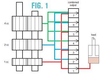
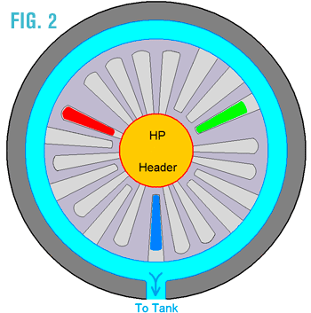
 Here is one method of doing this, illustrating the use of a shift valve or plate to direct the output of three different sections to the load. Fig. 1 is a simple view of three gear pump sections, their outlet paths, a directing shift plate or valve, and the load, shown as a piston – cylinder device. The three pump discharges, shown red, blue, and green, are directed to a chamber in a “Y” configuration, 120o apart, as shown in Fig. 2. A divider or indexing plate (or valve – call it as you wish) separates not only the individual pump outlets, but also directs those outlets to either the common load discharge header (in the center of the illustration) or to the reservoir (back to tank). In this example, you could choose a pump output from one through seven cc per revolution, and, of course, zero cc if you turned off the drive. Note that in the illustration, only the lowest displacement section (the red) is discharging to the HP header (the center), and the other two are open to the perimeter, which drains to the reservoir.
Fig. 3 is an illustration of how this divider or indexing plate might appear by itself. Sort of a snowflake that has had its DNA abused, I suppose. It would be rotated clockwise in seven possible steps to achieve the desired flow, adding a bit more capacity with each indexer movement.
For more information, contact Stephen at steve.white@parker.com.