4 Steps to Identify Hydraulic Threads
By Burleigh Bailey, Engineering Manager, Parker Tube Fittings Division
Machines and equipment are designed and manufactured in every corner of the world. The hydraulic systems alone use countless different types of fittings and adapters with different sealing methods and thread forms. While the sealing method can often be distinguished by appearance, thread forms all seem to look the same, making it difficult and time consuming to identify them when equipment modifications or repairs are needed.
Knowing the correct thread is critical for selecting the right replacement parts for maintenance and repair. Selecting the wrong part can result in damage to the thread during installation, which compromises the pressure holding capacity and seal reliability of the fitting or adapter. Quickly and properly identifying threads can help maintain safe, productive, and profitable operations.
There are six types of threads commonly used on hydraulic tube fittings: UN/UNF, NPT/NPTF, BSPP (BSP, Parallel), BSPT (BSP, Tapered), Metric Parallel, and Metric Tapered. Four simple steps will help you identify them.
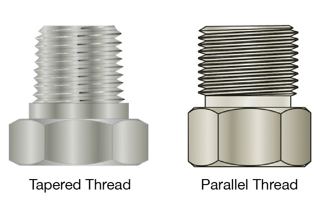
Step 1: Determine if the thread is tapered or parallel. NPT/NPTF and BSPT are tapered threads while UN/UNF and BSPP are parallel. Metric tapered and metric parallel speak for themselves. In some cases, step 1 can be accomplished by visual inspection alone. Tapered threads get smaller in diameter toward the end of the fitting while parallel threads maintain the same diameter from start to finish. If this is not obvious by looking at the fitting, use the parallel jaws of a caliper to make a comparison. Furthermore, the presence of an O-ring or the removal of a tube nut is usually an indication that the male thread is parallel. Completion of step 1 will eliminate three of the six possible thread forms.
Step 2: Determine the pitch. This can be deciphered using a pitch gage for comparison or by accurately measuring and calculating the number of threads within a given distance. It is much easier to compare threads against a lighted background with a pitch gage. Because some thread pitches are relatively similar, it is advisable to try a number of gages before deciding which one fits best. The result from step 2 will narrow down the possible thread forms even more because most have a distinct pitch. Consult the step 2 column in table 1 for possible pitches.
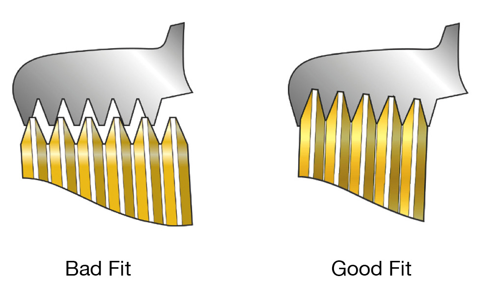
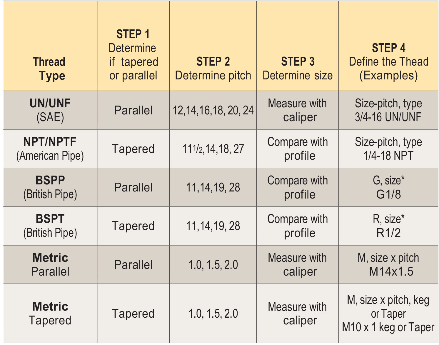
Table 1. *For JIS (Japanese industrial standards), the thread can be identified similar to BSPP and BSPT but defined with PF and PT, respectively. For example, PF 1/8 and PT 1/2.
Step 3: Determine the size. Combining the results of steps 1 and 2 will determine – or help predict, in some cases – the correct procedure for step 3. There are two methods for
determining the thread size; which to use depends on whether the thread is a pipe thread (NPT/NPTF, BSPT, BSPP) or is not a pipe thread (UN/UNF, metric parallel, metric tapered). Keep in mind that tapered (as determined in step 1) does not necessarily mean that it is a pipe thread (e.g., metric tapered). Likewise, pipe thread can be parallel (e.g., BSPP).
For pipe thread, determine the size by comparing it with a nominal size profile, as shown in figure 1 (a useful tip – pipe sizes up to 2-inch nominal size can be determined by measuring the actual outside diameter, subtracting a quarter inch, then rounding off). For nonpipe thread, the actual size can be determined by measuring the outside diameter (major diameter) with a caliper, as shown in figure 2.
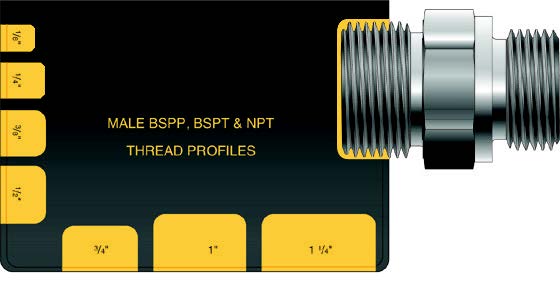
Figure 1: Determine pipe thread size with nominal size profiles.
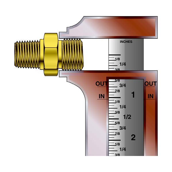
Figure 2: Determine non-pipe thread size with a caliper
Step 4: Designate the thread. Technically, this final step does not pertain to identifying the thread. Rather, it is a method of designating the thread type in an industry standard format for others to understand. Examples of the various formats are shown in the step 4 column of table 1. These typically have an indication of the thread size (whether nominal or actual), the type and, in some cases, the pitch.
Your company’s maintenance and repair professionals can put this easy four-step process to use to minimize machine downtime, avoid the expense of acquiring (and returning) incorrect parts, and help ensure a safe, accident-free work environment.
For more information, visit www.parker.com.
Share this information.
Related Posts
Canfield Connector Develops Custom Design for Conveyance Technology

What Is a Deutsch-Style Connector and Why Is It Important To Pick the Right One?

Tailoring Comprehensive Filtration Programs to Meet Your Needs
Replacing & Aligning a Hydraulic Cylinder

Rethinking the Hydraulic Reservoir

Fluid Power, Resolute as Gold
Sponsor

Sponsors