All About Vacuum: Sizing Vacuum Components
By Dane Spivak, Engineering Manager, Davasol Inc.
The design principles of most fluid power systems and vacuum gripping systems are governed by flow rate and pressure. There are numerous potential solutions for applications, though an ideal design would consist of efficient energy use and low project and maintenance costs. This article highlights the strategic thinking of sizing vacuum gripping components based on the aforementioned notions.
To begin, let’s analyze vacuum cup sizing and how it affects other areas of the system. When gripping a smooth surface where a cup can seal “perfectly,” such as glass or sheet metal, the maximum vacuum level is easily achieved as there is no leakage. This makes for easy sizing of the vacuum cups because you can calculate the gripping force using the cup diameter and final vacuum level reading. After considering the safety factor, you can determine the vacuum cup accurately. Using cups smaller than the target size results in an unsafe or incapable system, and anything larger is unnecessary overkill and additional cost.
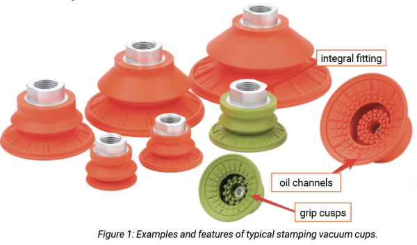
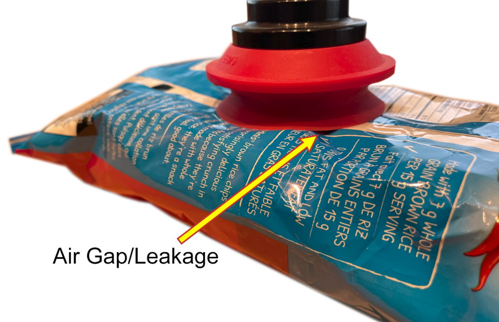 When considering gripping a product surface that is uneven or porous, such as a cardboard box, bags, or packaged food, suction cup sizing becomes more tactical. Due to the nature of the product surface, cups are unable to create a perfect seal. Air leaks between the cup and product surface and gets sucked into the vacuum system, as shown in figure 1. This is what is known as leakage, which reduces the vacuum level pressure and gripping force. This is an exaggerated example where the leakage gap is clearly visible, though often the gaps are very small but also extremely impactful to the final vacuum level.
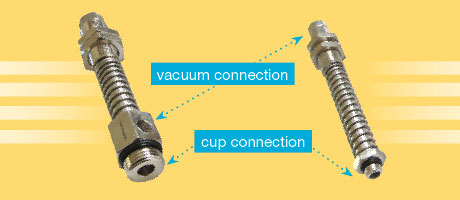
Reducing leakage as best as possible in a gripping system is usually ideal, as it produces higher vacuum levels and gripping forces. You should first select the right style and material of cup to grip the product, but then sizing the right diameter is a close second. A common trend with vacuum cups is that larger diameter cups have thicker lips that do not seal as well on uneven surfaces compared to a smaller cup with thinner lips. Additionally, larger diameter cups have larger perimeters, allowing opportunity for more air to leak into the system. That said, although larger diameter cups can theoretically provide more gripping capacity, leakage may result in reduced gripping forces or none whatsoever. Figure 2 shows two cups with 2-inch and 3-inch diameters. The 2-inch cup experiences less leakage and therefore a higher vacuum level and gripping force.
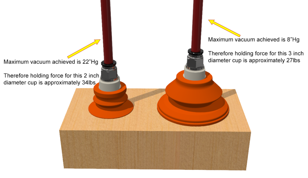 Referring to figure 2, there are techniques to increase the vacuum level of the 3-inch cup. A larger flowing pump can compensate for the air leaking into the system by pulling it out faster and reaching a higher vacuum level as a result. However, that requires an increase in pump cost, energy consumption, and overall system size to handle larger flows. For those costly reasons, increasing the pump size should only be done if necessary. Therefore, finding the right cup and tool for the application is crucial to the bigger picture; it determines the required parts for the rest of the system. Comparably, you would never use a crane to lift a small brick. Perhaps this is an exaggerated analogy, but it paints a similar picture.
Vacuum pump selection and sizing go hand in hand with the vacuum cups; they both depend on one another. If we revisit the concept of gripping smooth parts such as glass or sheet metal, the flow of the vacuum pump would be of interest. Since this would essentially be considered a closed system, the vacuum pump will reach near its maximum vacuum level so the flow will determine how quickly it gets there. Typically, these systems would require relatively small and lower flowing pumps unless the cycle rates are very fast. If the volume of the system is known, you can make theoretical calculations to estimate the evacuation time to reach certain vacuum levels.
The table above shows sample data collected from a vacuum gripping test in which the target vacuum level is 24”Hg. At 1 cfm the vacuum level reading is zero, which means the pump is unable to produce a vacuum level because there is more leakage entering into the system, and it cannot pump out enough air to quickly create a pressure differential. As we move up to 2 cfm and 5 cfm, we see the vacuum level start to climb. At 8 cfm the target of 24”Hg is met, which, based on this data, would be the minimum requirements. If the system is small, simple, and reliable, the 8 cfm pump would be a good choice. The reading of 25”Hg at 10 cfm is a touch higher in performance than needed but is also an attractive choice if the system has potential losses or the pump might lose performance over time. Lastly, the 15 cfm appears to offer no benefit; it is nearly double the flow than required and too much of a safety buffer offering little to no returns. A pump that large would simply be a waste of cost and energy. Note that this hypothetical set of data does not relate to larger centralized systems with potential leaks and losses and is simply an arbitrary and conceptual example.
The lower flow points in the table data are extremely valuable. Without them, a flow of
30 cfm could have been tested and found to work well. But that would result in a pump with three times more flow than needed. Oversized pumps are not uncommon for this reason. If we revisit the crane analogy, this would be similar to deliberately using a crane to pick up a small brick simply because you know it will work. Luckily, some pump model performances are adjustable using techniques such as regulating the compressed air pressure on air powered venturi generators, using variable frequency drives, relief valves, or other external adjustable devices. These can help save energy if the pump is unnecessarily overworked, or, on the other hand, it can help increase flow and vacuum level if a pump is undersized. Approval from the pump manufacturer should be confirmed before proceeding with such changes.
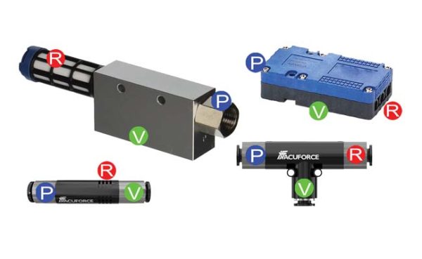
We have discussed the importance of sizing cups and pumps. We are left with everything in between, which includes parts such as fittings, hose, valves, and filters. The parts themselves have their own purpose. But from a sizing standpoint they all follow the same rule, that golden rule being sizing each part to have the ability to allow air to flow through the system effectively to minimize losses or restrictions between the pump and the cups. In a few words, flow rating is most important. If components are oversized, the system will have too much volume, which would take more time to pump out air and reach desired vacuum levels. Not to mention theadditional costs involved. If the components are undersized, the system flow is restricted and cannot breathe freely. This would mean the pump is unable feed the vacuum cups its maximum potential performance and would be consuming excessive energy. A vacuum system is only as strong as its weakest point. If there is one part in line with the system flow that is undersized, it affects the rest.
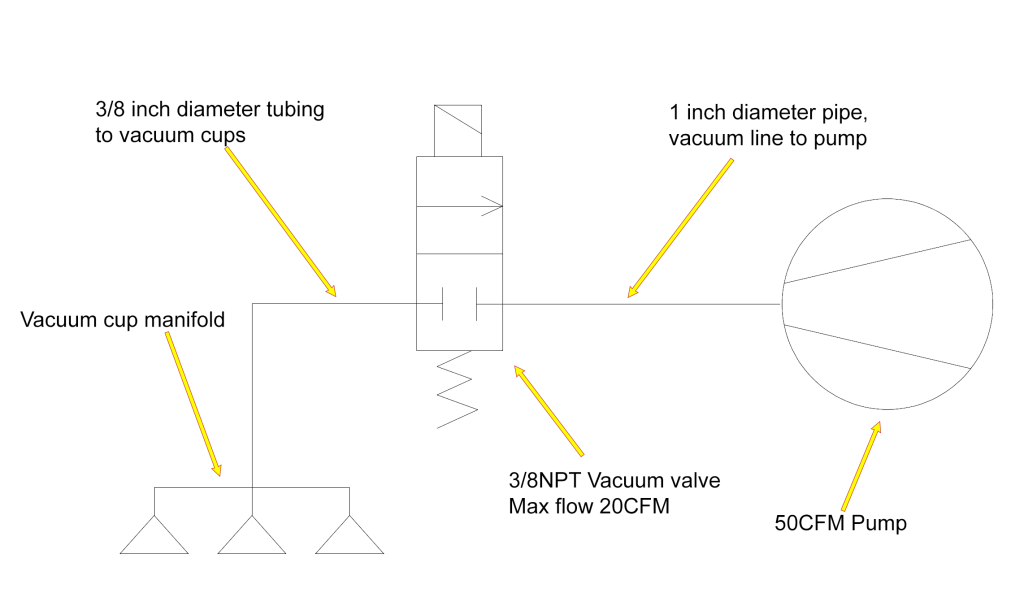 Figure 3 shows a system with an undersized valve. The pump is producing 50 cfm, while the valve is only capable of handling 20 cfm. Therefore, 30 cfm of performance is lost since the valve is restricting the potential flow produced by the pump, which prevents the cups from accessing the complete available flow. Back to the crane example, if the crane has a strong base and lifting device capable of handling heavy loads, but the beams cannot handle nearly as much, it becomes ineffective because the beams prevent the base and lifting device from carrying their maximum potential weights. A solution to the vacuum valve restriction would be to use a 50 cfm+ valve or perhaps use three 20 cfm valves in parallel, which would equate to 60 cfm.
Flow and vacuum level are the key performance factors in vacuum gripping systems. The sizing of each component can affect these factors in applications, so strategic selection is critical to the final design. Each application presents a new set of challenges, and professional advice is recommended for the right solution. •
This article is the opinion of the author, Dane Spivak of Davasol Inc., an industrial brand management firm. One of Davasol’s clients, Vacuforce LLC, based in Indianapolis, partners with the author on this article. Contact Dane Spivak at dspivak@davasol.com.
Share this information.
Related Posts

Sponsor

Sponsors