Analyzing a Hydraulic System Performance: If You Study It, You Can Improve It
By Tim Gessner, Delta Computer Systems Inc.
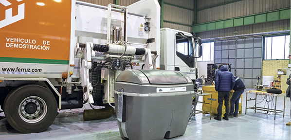
 To improve how a hydraulic system works, including reducing the amount of energy it consumes, you need to record and analyze data on how it currently operates and analyze it. That’s what Luis Javier Berné8 of IhBER S.L. of Zaragoza, Spain is doing. IhBER designs hydraulic systems and distributes hydraulic system components. The company previously developed the designs for all of the hydraulic controls of a side-loader refuse truck (see Figure 1), including the control system that powers the lifting arm. Though the system works fine, IhBER engineer Berné has been analyzing its operation to see if it could be improved. Berné’s work played a large role in his studies leading to a Ph.D. at Universitat Politécnica de Catalunya, LABSON Fluid Power Laboratory, in Terrassa (Barcelona), Spain.
“Our original hydraulic design objectives were fulfilled satisfactorily, but I’m very interested in energy efficiency and we want to continuously improve the system to stay ahead of our competitors in that regard,” said Berné. “A key metric is fuel consumption. Our current design needs 55% less energy for the same machine cycle in the same conditions in comparison to the newest truck of the most important competitor, but there is still a big potential for improvement.”
Factors under study
“The first step in my analysis is to identify the main energy losses in the current hydraulic system,” said Berné. “The second step is to create and validate a simulation model of the current system. Finally, I will propose different innovative solutions in the simulation model and analyze their impact on the energy efficiency.”
The most significant sources of energy loss being analyzed by Berné include:
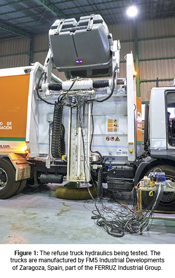
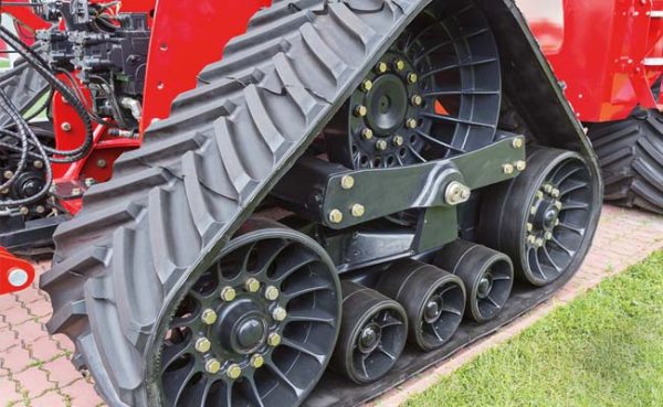
- Losses due to moving several actuators (Figure 2) at the same time with only one pump. The pump must guarantee the highest pressure demanded by the actuators, so in the less loaded actuator lines, there is energy loss. It is not easy to minimize these losses without using one pump per actuator, and this solution would be very expensive.
- Losses associated with the control of positive (overrunning) loads. Theoretically, an overrunning load (i.e., a load moving under its own weight or momentum) doesn’t need energy to be moved, but actually most hydraulic systems spend a lot of energy to control the load accelerations or decelerations (e.g., creating back pressure, throttling return flow, feeding oil to the opposite actuator chamber, etc.).
- Energy needed to move the system without the refuse bin (the weight of the lifting arm structure itself).
Data acquisition solution
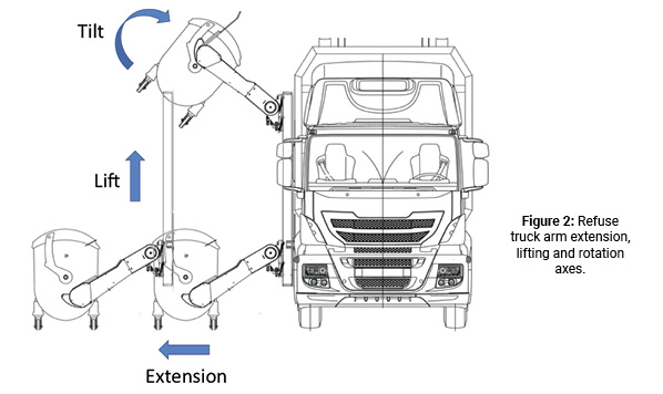
In order to do his work, Berné needed a solution for data acquisition that could handle lots of channels with a high sampling rate. He selected the RMC200 multi-axis motion controller, which at first glance, may be a surprising choice to use in a data acquisition application that by itself doesn’t involve controlling motion. “But high-performance motion controllers are designed to gather sensor data with high precision and at great speed,” he said. “Another reason for choosing to use a motion controller is because when the analysis and simulations are complete, I will update the controls of the real hydraulic system with the new solutions. I chose the RMC200 because it is easy to use and the software provided with it has powerful plotting capabilities.”
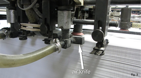
The RMC200 controller can handle position and pressure/force control of up to 32 motion axes simultaneously, which translates to the ability to interface to up to 64 total position or pressure transducers. In the case of Berné’s system (see Figure 3), the RMC200 processor was built out with five A8 cards, each offering up to 8 analog input channels, for a total of up to 40 possible data points analyzed.
“In order to study the energy consumption of the refuse bin lifting system, I need to measure and record, in different load conditions, the actuator positions (to calculate actuator speeds and thus flows) and pressures at several circuit points,” said Berné.
Analyzing the data
Figure 4 shows the positions of all of the axes, plotted over time using plot manager software. In addition to axis positions, Berné also used this software to plot system pressures, looking for anomalies.
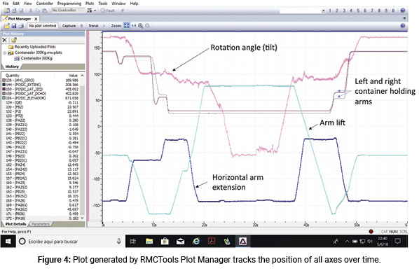
“Besides monitoring the raw positions and pressures around the system, I can filter signals and calculate flows and power losses in the loop,” Berné continues, “and the RMC200 gives me the results just after the measurements are made, without needing to spend a lot of time in signal post-processing.”
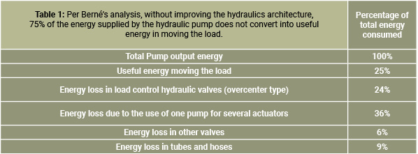
The tests allowed Berné to clearly identify the sources and magnitudes of the energy losses with different loads (see Table 1). Now he is working on developing solutions using a mechatronic modeling and simulation package called 20-Sim from Controllab Products B.V. in the Netherlands.
Prototyping different architectures
Berné’s next step is to build a real prototype using the hydraulic system configurations that offer the best performance as indicated by the simulation data in order to verify the results using the real hardware.
The existing refuse-lifting hydraulics uses a variable displacement piston pump and a load-sensing proportional valve. “Even though load sensing with proportional valves is commonly used elsewhere in the hydraulics industry, it is by far more efficient than what our competitors have been using,” said Berné. “Yet we believe that a different system architecture may be even more efficient, enabling our customer FM5 to maintain their competitive advantage well into the future.”
New architectures offer more control flexibility
Berné is experimenting with hydraulic system architectures that incorporate multiple proportional valves (see Figure 5) instead of using one proportional valve, the use of several simple proportional valves (for example, 2/2 cartridge proportional poppet valves), one valve per path: P to A, P to B, A to T, B to T, and sometimes A to B (regeneration). This enables fluid paths to be opened in different percentages, allowing pressure drops to be tailored to lower a load without needing to supply fluid flow in the opposite actuator chamber.
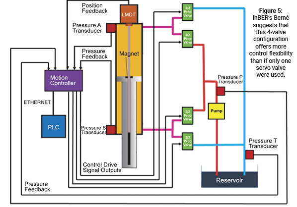
The system shown in Figure 5 is more difficult to control (four or five output signals needed instead of one), but the flexibility is considerably higher. “Flexibility means for me that there are lots of valve opening combinations to consider in setting control levels to minimize energy consumption,” said Berné. “Control of such a system would be difficult with a conventional mobile controller, but the multi-axis control capability and the use of visual programming tools that the RMC200 controller offers will make the work much easier.”
The cost of the refuse bin dumping system using the new system architecture doesn’t need to be much higher because 2/2 proportional poppet valves are less expensive than the spool ones that were previously used, and the added cost of the new multi-axis motion controller will be more than compensated-for by the increased fuel economy.
Share this information.
Related Posts


Sponsor

Sponsors