Calculating the Hydraulic Pressure to Support Jib Boom Loads
The jib boom is an example of a third class lever. That is, one end of the lever rotates about a stationary pivot, the cylinder acts against the lever somewhere between the two ends, and the free end of the lever is used to move the load.
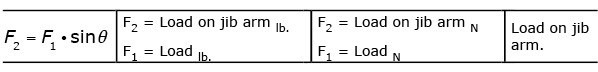
Solving jib boom crane problems (such as the example illustrated in Fig.1) for the force acting against the cylinder rod, requires solving for the vertical load at the fulcrum. Then, solve the right triangle for the force that acts against the cylinder on a line through the center of the rod.
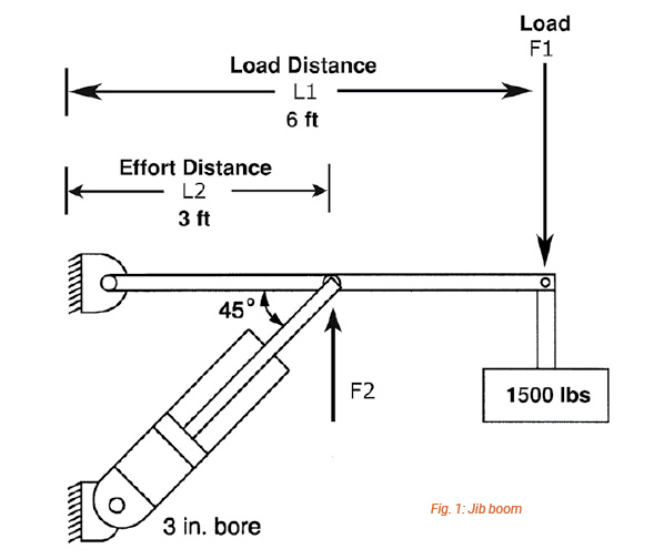
For example, if the load at the end of the jib boom is 1,500 lb., the vertical load at the end of the cylinder rod can be determined from the balance of forces on the lever as in Fig.1.
F2 = 1,500 lb. • 6 ft. / 3 ft. = 3,000 lb.
The force acting against the end of the cylinder rod can be determined by solving the right triangle formed by the cylinder, the beam, and the wall, using trigonometric functions.
Fcyl = 3,000 lb. / 0.7071 Fcyl = 4,243 lb.
In Fig.1 the beam is horizontal, the support is vertical, and the clevis mounted cylinder is mounted at one of the standard angles: 45°, 30° or 60°. This is usually not the case. As soon as the cylinder rod moves the beam, the angles change. For example, in Fig.2 the beam is shown 45° from the horizontal while the cylinder is mounted to a horizontal ground support at a 30° angle to the beam. Moreover, as the cylinder rod extends and retracts the angles will constantly change. What will not change is the direction of the force to move the beam which always acts perpendicularly (at 90°) to the beam.
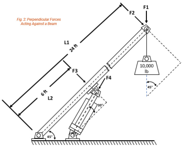
The dotted lines shown on Fig.2 identify right triangles that can be solved to calculate the magnitude of the forces that act perpendicularly to the beam. To solve problems of this type:
- Use the vertical angle between the load and the boom to compute the load that acts perpendicularly to the end of the beam.
F2 = 10,000 lb. • 0.7071 = 7,071 lb.
2. Calculate the mechanical advantage of the load at the end of the beam, compared to the load that acts perpendicularly to the beam at the cylinder rod end pin.
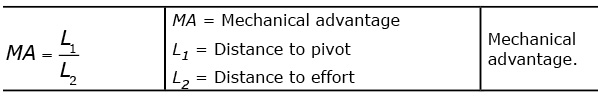
MA = 24 / 6 = 4
3. Calculate the load that acts perpendicularly to the beam at the rod end pin.
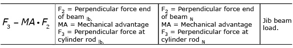
F3 = 4 • 7071 lb. = 28,284 lb.
4. Calculate the load supported by the cylinder (F4). Use the equation for Fcyl
Fcyl = 28,284 lb. / 0.50 = 56,568 lb.
Share this information.
Related Posts


2 thoughts on “Calculating the Hydraulic Pressure to Support Jib Boom Loads”
Leave a Reply
Sponsor

Sponsors
the lengths of the vertical post and jib of a jib crane are 6.5 and 7 m respectively, and the angle between the post and jib is 40° a mass of 2.854 t is suspended form a wire rope which passes over a pulley at the crane head and then led down at an angle of 50° to the vertical to a winch behind the post .draw to scale the vector diagram of forces at the crane head and measure the forces in the jib and tie”
IN FIG 2 DIRECTION OF FORCES F2 AND F3 TO BE UPWARD