Case Study: Building an Industrial Hydraulic System
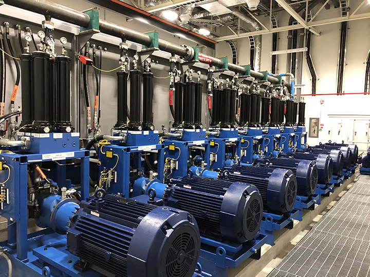
Eight of the sixteen pump/motor groups.
By Steve Misiakowski, Engineering Director, Exotic Automation & Supply
Designing a large central hydraulic system to support a new 138,000-square-foot industrial facility presents many unique challenges compared to the more common practice of designing hydraulic power units for OEM machine builder’s equipment. As this article shows, such a significant project for one of our customers presented similar key design challenges and considerations.
The customer’s new greenfield facility is a test lab responsible for structural advanced life-cycle testing. There are dozens of individual test locations throughout the building, each presenting unique hydraulic actuation requirements to facilitate the necessary tests. The customer’s goal was to partner with a turnkey supplier to design, construct, install, and commission a large central hydraulic system capable of providing stable hydraulic oil pressure at variable volumes.
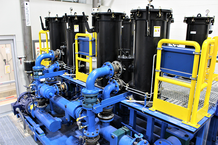
Recirculation skid for kidney loop filtration.
The problem
The customer’s existing central hydraulic system had been designed and installed 35 years ago. That installation included fixed displacement gear pumps to provide flow and pressure throughout the facility. A great amount of energy was continuously wasted in the form of heat generated by oil flow over relief valves at the pump units. Most of the test rigs throughout the facility included high-precision, high-speed servo valves that were sensitive to fluid contamination. Since the hydraulic system wasn’t airtight, the company couldn’t control the ingress of contaminants into the hydraulic fluid. The contaminated oil resulted in expensive, weekly repairs to maintain the servo valves. After 35 years, the customer knew what it wanted for its new building: an energy-efficient system that reduced component repairs and increased overall system uptime.
The requirements of this new central hydraulic system were very detailed and, in many instances, much more stringent than typically seen in general industrial hydraulic applications. The specs included:
- Precise control of a large volume of fluid (over 18,000 gallons)
- Flow variation up to 250 gpm in as little as 200 milliseconds
- Stable system pressure (3,000 psi, + 0 psi/-100 psi) at variable volumes of 0-2,200 gpm
- Engineered (nonwelded) piping
- Maintain oil temperature between 112°F and 130°F during operation
- Oil cleanliness of ISO 12/10/7
- Water content in the oil below 10 ppm
- 24/7 year-round operation with a life expectancy 30-plus years
Other than known limited space constraints in the design for the pump room, concepting the hydraulic portion of the project began with a blank sheet of paper. We presented multiple concepts and detailed proposals that included 3D CAD models over the course of 12 months before the project was finally awarded. It took 4 1/2 years from initial inquiry to final customer acceptance.
The project involved many stakeholders. Countless design review meetings with the facility’s general contractor, design architects, structural engineers, representatives of other building trades, and the end user resulted in a system with the following major components:
- Reservoir (11,000-gallon capacity) with closed loop air exchange
- Pump/motor groups with duplex pressure filtration manifolds (360 cc pumps coupled to 16 300-hp motors)
- Recirculation and cooling skid
- Roof-top heat exchanger (6 million BTUs)
- Vacuum dehydrator and particle counter
- Return filter skid
- 20 accumulator stands, including 104 15-gallon bladder accumulators
- About 10,000 feet of engineered piping
- Controls architecture, including soft-starter panels, variable frequency drive panels, programmable logic controller panel, operator interface, I/O handling, sensors, and alarms
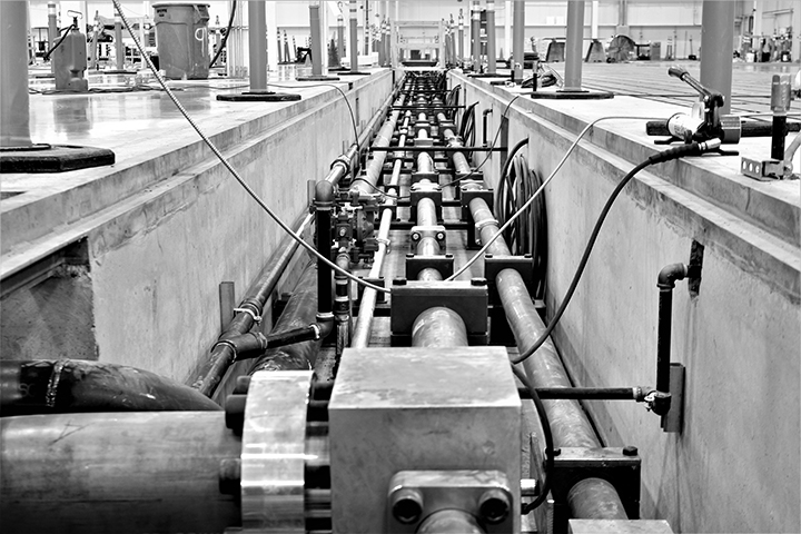
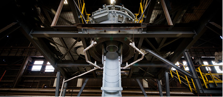
The engineered piping trench.
Design challenges
There were a number of unique characteristics and design challenges for each of the system’s major components.
Reservoir. The highly engineered reservoir had to be large enough to support the variability of worst-case operating and emergency-stop scenarios. The final dimensions of the reservoir were 7 feet high by 7 feet wide by 35 feet long.
The real challenge to designing this large 304-stainless steel reservoir was handling the velocity of return oil flow. We installed a custom 8-inch schedule 40 pipe with hundreds of 1-inch holes as a diffuser down the center of the tank. This effectively “calmed” the return fluid while minimizing aeration as it mixed with the tank’s volume. We incorporated numerous baffles to separate the return oil coming into the center of the tank from the pump inlet supply fluid outlets on either side.
This was truly a unique hydraulic reservoir that required a structural 3D CAD model, finite element load analysis of the reservoir lid segment, accommodations for pressure testing, and multiple locations for level and temperature
sensors. Once built, it required exterior sugar blasting followed by a clear-coat application.
Pump/motor groups. We were challenged to design a system that eliminated the user’s ability to perform manual tweaking of the components.
The pump solution for the new central hydraulic system included pressure-compensated pump technology with load sense control for 24/7 year-round operation. Partnering with Parker Hannifin, we delivered a custom pump control scheme. Parker’s experience with large system applications and its load-sharing expertise led to a solution that included 16 360-cc displacement Parker PVplus Series pumps with load sensing control and electrical unloading.
While piston pumps were more expensive than the gear pumps in the customer’s existing hydraulic system, they provide longer life operating at higher pressure and longer continuous duty cycles. The load sensing system generates fewer power losses because the pump reduces both flow and pressure to match the load requirements of the system.
Each of the 16 pumps was coupled to a 300-hp inverter-duty-rated motor. These pump/motor groups were each incorporated into free-standing drip trays that supported a custom pressure filter manifold that held two duplex filter assembles rated to 5,000 psi with 3µ filter elements. We placed eight pump/motor groups on each side of the large main reservoir.
Recirculation and cooling skid. Another significant challenge was meeting the stringent oil cleanliness requirement of 12/10/7 per ISO 4406:99. An oil recirculation skid, or kidney loop filtration system, was needed. This recirculation skid provided a continuous flow of oil filtered at 2µ separate from the main supply pressure filters, and directed the filtered oil up to the 6 million BTU heat exchanger (cooler) located on the roof of the new building.
Roof-top heat exchanger. The large heat exchanger on the roof was exposed to weather conditions typical of the Midwestern U.S. – from subzero winter temperatures to 125°F in summer. With oil returning to the reservoir at 140°F, the challenge was to maintain the oil temperature between 112°F and 130°F during operation, regardless of weather conditions outside.
The solution was to have the recirculation skid’s pumps individually cycle on or off as needed to keep the hydraulic system’s temperature regulated. We accomplished this by having each of the four screw pumps on the recirculation skid controlled with a variable frequency drive. The VFDs provided precise speed control (flow control) and energy efficiency. Since the fluid temperature was being monitored in numerous places throughout the hydraulic system, we could program the amount of fluid cooled by the rooftop cooler and the running of the cooling fans to effectively keep the oil temperature in the proper range during operation.
Vacuum dehydrator and particle counter. Water is one of the most common and detrimental contaminants of industrial oils and related equipment. Water vapor enters the oil and condenses when temperatures drop. It depletes rust inhibitors and can cause direct corrosion of steel components in the hydraulic system.
We overcame this challenge by incorporating a properly sized vacuum dehydration unit. Vacuum dehydration is the only comprehensive method to effectively remove water vapor and other dissolved gases from the oil. Through low-temperature distillation in combination with fine filtration, oils can be kept in “like new” condition.
The vacuum dehydrator designed into our system was a stand-alone unit mounted on a structural steel base with an integral drip pan. It is capable of processing more than 1,200 gallons per hour at 1,800 rpm and contains an inline particle counter to monitor the oil cleanliness level. Its PLC communicates via industrial Ethernet to the hydraulic system’s main PLC, sharing critical fluid data.
Return filter skid. Due to the central hydraulic system’s significant potential flow volume of up to 2,200 gpm, we combined two sets of large duplex filtration vessels on a single steel-base return filtration skid. Each of the four total vessels is populated with seven triple-length 20µ-filter elements.
Accumulator stands. With the possibility of sudden flow changes due to test stands starting and stopping, we had to account for the resulting “shocks” to the hydraulic system. The solution was to incorporate strategically located banks of accumulators that are used to absorb and store energy. We located 20 accumulator stands throughout the new facility to provide an evenly distributed amount of shock absorption capacity.
Engineered piping. Another challenge to overcome was avoiding the energy lost by improper plumbing. Selecting the proper line size for a hydraulic system is critical to obtaining maximum performance and life from hydraulic components. Undersizing fluid lines results in high pressure loss and heat; oversizing lines increases the cost of the system. In typical applications, lines should be sized as follows:
- Suction: 2-4 feet/sec.
- Return: 10-15 feet/sec.
- Medium pressure: 15-20 feet/sec.
- High pressure: 20-25 feet/sec.
We reduced these velocities to prevent excess energy loss.
The almost two miles of piping, located in floor trenches throughout the new facility, used 95% weld-free connection technology, eliminating the risk of corrosion due to stress cracks during welding and increasing the lifespan for the piping system. We used facility CAD data in conjunction with the CNC cold bending machines to manufacture the precise tube segments. Orientable flanges gave the pipe fitters greater flexibility during assembly. This reduced installation time and will simplify maintenance, reduce operating costs, and improve safety.
Providing proper line sizes means improved performance of the hydraulic test equipment throughout the facility. It makes flow more laminar, reduces the effect of shock, decreases potential leak points, increases fitting and connector life, and reduces heat generation.
Controls architecture. For this central hydraulic system, the controls design and integration were part of the turnkey installation. Operating the hydraulic system 24/7 year-round required redundant PLCs. We designed controls that would monitor, record, and respond to system performance and health. The items monitored and displayed on the system’s main operator interface included:
- 120 multiple emergency control stops
- System flows and pressure
- Reservoir fluid levels
- Oil temperature
- Multiple vibration sensors
- Multiple bearing temperature sensors
- Multiple differential pressure sensors (mainly across filters)
- Multiple sump alarms
- Valve position indicators
- Security inputs, such as fire alarm, smoke detector, and sprinkler water flow
- Fluid ISO particle count level, as well as water and air content
- Status of all the system’s pumps, fans, and motors
- The customer also required remote-access to the control system via their intranet to monitor, interrogate, or silence alarms. Having all user-editable parameters along with real-time system performance data located on the
password-protected human-machine interface greatly enhanced the customer’s efficiency in maintaining the system and maximizing uptime.
The project achieved the customer’s system requirements for flow response, pressure compensation, and energy consumption. The customer received a turnkey custom hydraulic solution tailored to their unique application. Parker was the source of many system components, including filters, valves, accumulators, KleenVents, proportional valves with controllers, hoses, and fluid connectors.
The results
We addressed all the customer’s issues related to the old hydraulic system:
- We improved the system’s energy efficiency with the variable displacement pumps.
- We achieved oil cleanliness of ISO 12/10/7, maintainable by a multistage filtration strategy.
- The cleaner oil significantly reduced repairs.
- The modularity of the system’s design and redundant controls led to documented reductions in system downtime.
Using sound fluid power design principals, the new central hydraulic system achieved measurable benefits with a much smaller footprint than the customer’s previous system.
Share this information.
Related Posts

Sponsor

Sponsors