Determine the Appropriate Solution to Control Air Cylinder Speed
Because air is a compressible fluid, controlling the speed of actuators is a unique problem. A pressurized air cylinder that is not under load will extend and/or return suddenly if the exhaust air is not controlled. This is often the case and is not likely to cause damage since most air cylinders are engineered with shock pads or incorporate external stops on the cylinder rod to prevent the piston from bottoming internally against the head and cap ends. Unlike hydraulics, most pneumatic applications require full extension or full retraction without an intermediate position.
It is necessary to understand the load dynamics that are present and to calculate the load ratio (LR) to achieve accurate speed control. This extra force, beyond the load force requirements, determines how fast the load can accelerate.
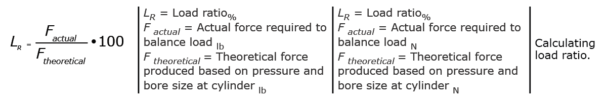
The load ratio should never exceed approximately 85%. The lower the load ratio, the better the speed control, especially when the load is subject to variations. To get a constant speed, the load ratio should be approximately 75% or less. If accurate speed control is required or load forces vary widely, 60-70% should not be exceeded, perhaps no more than 50% in vertical applications.
A positive speed control is obtained by throttling the inlet or exhaust air of the cylinder by means of a speed controller, which is a combination of a check valve, to allow free flow towards the cylinder, and an adjustable throttle (needle valve).
Metering out is a common method for controlling double-acting cylinders. This is not to say that air cannot be metered into a cylinder to control velocity. However, unless a constant restrictive load is being moved, the cylinder will lurch as air pressure builds to the requirement of the load. Then the air expands suddenly in the cylinder, dropping the pressure, only to repeat the process and lurch again.
In some instances, the cylinder speed can be adversely impacted by the resistance created by the tubing and valving connected to the cylinder. To prevent the restriction of flow from delaying the response time of the cylinder, a quick exhaust valve may be employed. The quick exhaust valve connects directly to the cylinder port and allows for a large volume of air to exit the cylinder quickly to prevent dampened response times.
The rpm of air motors, on the other hand, is commonly controlled by the pressure at the inlet. Many air motors power constant loads, so it is as effective to regulate the inlet pressure as it is to provide a restriction at the inlet or outlet that wastes power needlessly.
The figure illustrates a double-acting cylinder mounted vertically with a load hanging on the cylinder rod. If the flow controls were to be reversed for meter-in control, the load would drop suddenly when the solenoid valve is signalled to lower the load. Meter-in flow control would cause uncontrollable lowering and a hazardous condition.
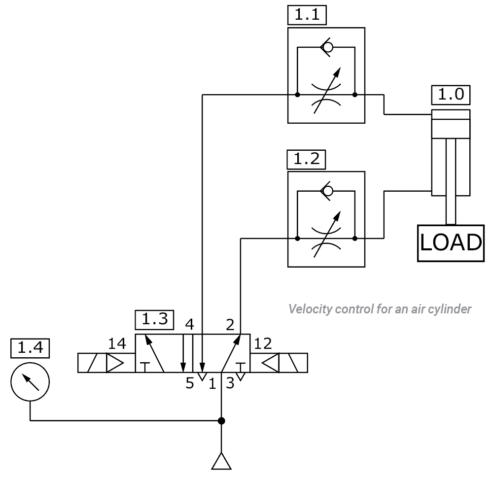
Notice there are flow control valves in each cylinder line of the circuit to control the velocity. Each flow control valve allows air to pass freely in one direction and to be restricted in the other. As the valves are configured in the circuit, shifting the power valve to raise the load allows free flow of air through the check valve to the rod end of the cylinder to lift the load. The flow from the cap end is restricted back through the control valve to prevent the cylinder from retracting suddenly should the load be removed. Shifting the directional control valve to extend the cylinder and lower the load directs air to the cap end of the cylinder through the check valve. Return air from the rod end of the cylinder must pass through the restriction, preventing the load from dropping suddenly. This is a meter-out circuit.
Test Your Skills
Referring to the figure, which valve configuration would require the lowest pressure while the load is being lifted?
a. Remove the flow control at valve 1.2.
b. Reverse flow control check at valve 1.1.
c. Reverse flow control check at valve 1.2.
d. Reverse flow control checks at valves 1.1 and 1.2.
e. Leave flow control valves 1.1 and 1.2 as they are.
See the Solution
The correct answer is b. The valve configuration as shown in the figure shows that valve 1.1 is installed so that when retracting the cylinder (raising the load) the return air is being metered-out with a speed control that imposes a restrictive force on the cap end of the cylinder. To remove this restriction, valve 1.1 should be reversed so that it is free flowing from the cap end of the cylinder.
Share this information.
Related Posts
Understanding the Selection Process of a Pressure Control Valve
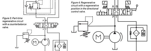
Test Your Skills: Understand the Application of Regenerative Circuits

The “STAMPED” Method
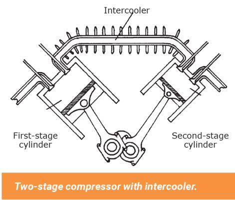
Test Your Skills: Types and Applications of Compressors

Test Your Skills: Stopping & Holding Loads Safely
Calculating Intensifier Ratio for Given Pressure and Flow
Sponsor

Sponsors