Don’t Choke!
One of the more confusing aspects of vacuum pick-and-place systems is vacuum flow. Flow in a vacuum system, like any other fluid power project involving compressed air or hydraulic oil, is a very important factor.
More often than not, a vacuum venturi or vacuum pump is oversized to compensate for a lack of understanding or a sub-standard installation. Consider this: the only reason for a different size of vacuum-pumping apparatus is to offer different speeds of evacuation. A 1-cfm vacuum venturi will do the same work as a 20-cfm vacuum venturi; it will simply take longer to do it. The cost to purchase and operate a vacuum system can be considerably reduced if the correct components are chosen for the application.
Flow in a vacuum system is often confusing to visualize for the compressed-air engineer. Vacuum is the reduction of atmospheric pressure in a fixed volume, such as a well-sealed vacuum cup or circuit. If it is not sealed well, there will be leakage. Then we do not have a fixed volume, and a vacuum condition is therefore more difficult to generate. If the pump is large enough, it could overcome the leakage around the cup or in the vacuum circuit, but this will immediately decay once the pump is turned off.
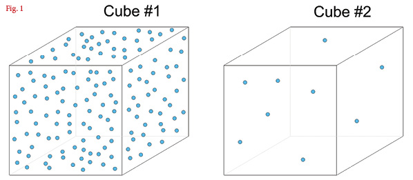
A known volume of atmospheric pressure is demonstrated in Fig. 1. Cube #1 is full of gas molecules and is at an atmospheric condition. Cube #2 is virtually empty of gas molecules and is at a vacuum condition. A vacuum could be defined as a known volume containing fewer gas molecules than an equivalent volume in the atmosphere around it. That’s what atmospheric pressure is: gas molecules bouncing against each other, creating pressure. Take them out of the known volume, and the pressure reduces or, in other words, a vacuum is created.
 If you place your hand near the exhaust of a vacuum pump when it initially starts, you will feel lots of air rushing past. As the vacuum increases in the volume attached to the pump, the airflow decreases. The reason is simple: fewer gas molecules are passing by your hand because there are fewer in the known volume. At a “full” vacuum, there wouldn’t be any airflow at all.
That’s vacuum flow: the flow of air molecules that are being removed from an atmospheric pressure volume.
So in practical terms, how do you size or select components for a vacuum system? The simple answer is to think of everything in your circuit, such as valves, fittings, hose, and tubing, operating at a total pressure drop of 15 psi or 1 bar(g). If you size to that specification, you won’t go far wrong, but the connection of these various components in a vacuum circuit is key. The following paragraphs offer some basic rules for the correct utilization of common vacuum components.
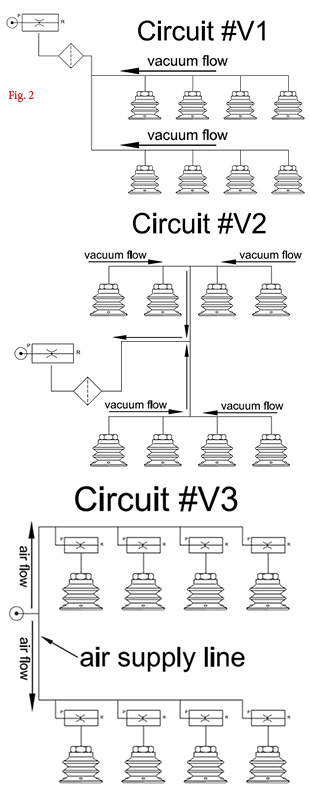
Consider Fig. 2. This circuit includes the following components: a single vacuum venturi, vacuum inlet filter, and eight vacuum cups. Circuit #1, depending on the distance and the diameter of the interconnecting tubing and/or fittings between the venturi and the cups on the far right, could suffer from “choking”—a condition where the cups on the right are starved of vacuum flow. This is a very common situation, particularly on larger vacuum circuits. A simple solution would be to increase the internal diameter of the tubing, which would reduce the restriction(s) and offer a balanced vacuum level across the circuit. The problem, however, is the time it takes for the vacuum venturi to evacuate the volume of tubing, particularly in a high-speed pick-and-place application. Circuit #2 offers a more balanced condition between all eight vacuum cups and is a simple modification to the system.
Circuit #3 shows the same vacuum cup circuit but with a dedicated vacuum venturi for each cup. This removes all potential vacuum flow problems and indeed offers a faster cycle time, but the user will now experience a potential compressed-air restriction in the supply lines if the tubing is not the right internal diameter. Another considerable concern could be the extra compressed-air consumption in comparison to circuits 1 and 2.
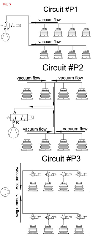 Fig. 3 shows the same circuits, but all of these would be used on machinery where a vacuum pump is the vacuum-generation device. Instead of poorly or well-placed vacuum venturi, vacuum valves are used instead. The same concerns would apply to distance and imbalance of piping and to consequent vacuum flow restriction. Of course, the same vacuum pump could be used, and therefore the energy being used, except for the coils on the valves, does not change.
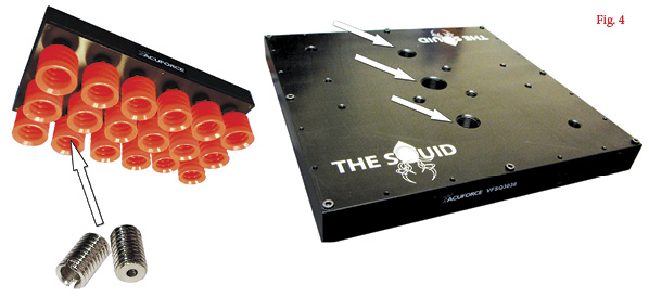
Fig. 4 shows a universal vacuum tool that utilizes an array of many vacuum cups to handle various loads, such as different-size boxes or products that vary in size.
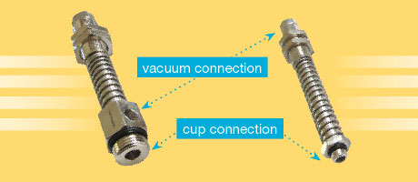
Because this array of vacuum cups requires an equal vacuum condition, flow is crucial in this particular application. The three arrows on the right-hand image highlight vacuum ports that connect to the vacuum source. This can be either a vacuum venturi or vacuum pump. If this universal vacuum-lifting head were being used in applications where various-size loads were being handled, some of the vacuum cups might not be sealed and would leak. The cups shown on the left-hand image all incorporate a small orifice screw as shown (enlarged) underneath. These small orifice screws incorporate a Ø1.5-mm (1/16-in.) hole that restricts the flow should the cup not be covered by the product being handled. To have a back pressure of 10″Hg on each of the open holes, the pump or venturi would need to generate about 1.5 cfm to 2 cfm of vacuum flow at 10″Hg. Therefore, if 10 cups were not covered, the pump would have to generate at least 15 cfm at 10″Hg to compensate for this leakage.
Some universal tools, such as the ones shown in Fig. 4, utilize a self-closing valve on each vacuum cup. If the vacuum cup attached to the self-closing valve is not sealed against the load, the induced airflow (leak) will shuttle the valve closed. The cups that are sealed against the load will have the full system vacuum level applied.
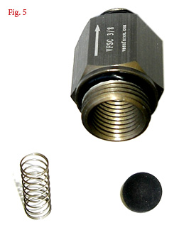
Each self-closing valve, as shown unassembled in Fig. 5 (body + spring + sealing ball + adjustment screw), requires between 0.5 cfm and 2 cfm to close. On a large vacuum cup array, many vacuum cups could be open to atmosphere when the head picks a smaller package, so consequently, a particularly large vacuum pump or venturi might be required. This could be cost or space prohibitive to the user. The circuit in Fig. 6 could be used instead of a large vacuum pump.
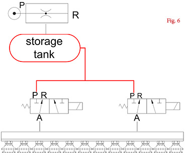
 This circuit uses a vacuum vessel or storage tank. The venturi or pump “charges” this tank to a high vacuum level. The tank and all interconnecting hose and fittings up to the vacuum valve inlet are evacuated to this high vacuum level (indicated by the red lines). When the control valve(s) open, the vacuum chamber is immediately evacuated with equilibrium created in the complete circuit, and if using the self-closing valve technology, they instantly close. Therefore, the venturi or pump size only needs to be able to handle the lifting of the parts, not the closing of the valves. This storage feature and vacuum control valve method considerably reduces the pump or venturi size and saves cost in purchase and ongoing ownership. If correctly sized, the pump could be as much as 90% smaller depending on the application because it is only used to recharge the tank during the non-lifting phase of the production cycle. If an automatic energy-saving system is also incorporated, the pump is shut off when the vacuum level is reached. This results in considerable energy savings.
What creates poor flow performance in a vacuum-lifting circuit? Valves that are too small or too far away from the cups, and hose and tubing that is too long or too small in internal diameter.
You’ll rarely have problems with flow if you use an oversized pump, but utilizing basic circuit fundamentals and understanding the components in use allows you to utilize the most efficient solution for the application.
This article is intended as a general guide and as with any industrial application involving machinery choice, independent professional advice should be sought to ensure correct selection and installation.
By Daniel Pascoe, Davasol Inc.
Vacuforce LLC is a manufacturer and distributor of vacuum components and systems for industry in North America. Vacuforce can be reached via its website (www.vacuforce.com) or directly at sales@vacuforce.com. Illustrations and 3D models supplied by Daniel Pascoe at Davasol Inc., an industrial distribution branding company. Daniel can be reached at dpascoe@davasol.com.
Share this information.
Related Posts


Sponsor

Sponsors