Gear Pump Load Sense
 A hydraulic distributor hired a sales engineer for a new territory they were moving into. The first customer the engineer visited requested a quote on a hydraulic system. The customer provided the following requirements to press two large forgings together:
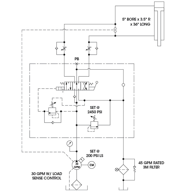
- 5” bore cylinder with a 3.5” rod, 36” long
- DCV, 3-position with a return “kick back to center” feature, manually operated
- Flow controls on both cylinder ports
- Return line filtration
- A pump that delivered 30 gpm at 2450 psi (not piston-type)
- No heat exchanger, if possible (The customer was going to build a larger reservoir than normal.)
- Electric motor had to be 230 volt, 3-phase, 60-cycle, C-face with coupling assembly.
- All parts needed to ship loose for the customer to mount and plumb on his machine.
The sales engineer designed the circuit and quoted the customer a price to deliver all of the components. The customer installed the parts using the circuit supplied. The sales engineer then got a call from the customer stating that the gear pump was overheating. It also seemed as if the load sense worked when retracting, but when extending at no load, was always at 2450-psi system pressure. The return line screw-on filter element was coming loose, and the customer had to keep tightening it.
Any idea what’s causing the problems?
See the Solution
When using load-sense circuits, it’s important to locate the sensing line where it will always sense the load pressure required to move the cylinder. The shuttle valve location on the circuit should have been between the DCV and the flow controls. When the cylinder is extending, the rod pressure can be twice the cap pressure due to the meter-out flow control causing the load sense to go above the main relief setting. Also, the filter was undersized, since a 2-to-1 ratio cylinder will return twice the pump flow at full speed when retracting, causing the element’s thread stud to stretch and eventually blow off.
By Robert Sheaf, CFPAI/AJPP, CFPE, CFPS, CFPECS, CFPMT, CFPMIP, CFPMMH, CFPMIH, CFPMM, CFC Industrial Training

One piece of the puzzle is a return filter which is too small. Amplified flow when retracting the cylinder is nearly 60 gpm. Too much for a 45 gpm filter.
The valve is a closed centre valve so there is potential for a signal to be locked in the load sense line which in turn will keep the pump pumping all the time. The flow control valve on the rod side of the cylinder may require adjustment to lower the pressure or restrict the flow going into the piston side of the cylinder as there may be pressure intensification happening on the extend of the cylinder as the circuit stands now.
The pump is load sensing but FIXED displacement so all flow not required to do useful work is bypassed to tank at system pressure + 200PSI (LS setting), which means heat generation.
The flow controls should be installed meter-in instead of meter-out.This would prevent pressure intensification on extension, hence the high pressure reading.
Maybe I’m missing something but the solution does not make sense to me.
The first thing I would do is to change the meter out needle valves to meter in, that way there will be no pressure intensification from the large piston side pushing oil out via the smaller area rod side. Having done this, I would leave the shuttle valve where it is.
In the solution posted by FPJ I don’t see how just moving the shuttle valve would make any difference.
Load sense line should connect to pilot relief valve so it unloading circuit will work during retraction and extension . Pilot relief work during retraction due to back pressure from filter since outflow is more than 45 GPM.