The Importance of Fluid Cleanliness in Today’s Heavy Machinery
By Robert Ihrig, Applications Engineer – Filter Systems, Hydac, Anthony Maiolo, Applications Engineer – Utility, and Timothy Rodman, Marketing Supervisor, Schroeder Industries

Heavy Machinery? More like Heavyweight Hydraulics!
In today’s modern equipment, simply maintaining fluid cleanliness in hydraulic systems can reduce the cost of operation by as much as two-thirds. This means improved uptime, higher performance levels, and reduction in cost of operation.
While operators rely on modern equipment to get the job done, what does modern equipment rely on? The answer: A highly efficient, reliable, and robust fluid power (hydraulic) system.
Old School vs. New School
Fluid power, as an energy source, can produce high power and higher forces in small volumes compared to electrically driven systems. Now, an average front loader can lift upwards of 2,000 lbs. at a time.
But My Fluid Looks Clean
Often times, the contamination causing the most issues in your equipment is not of a size easy to view by the human eye. Most everyone’s fluid “looks clean,” but is in fact riddled with contamination.
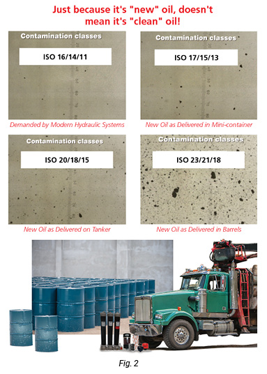
Particulate contamination of all sizes can originate from many different sources, such as:
- Oil containers delivering “new” oil
- Original equipment delivered by the OEM
- Poor cleanliness standards maintained during equipment operation (e.g., ingression of contaminant from damaged seals or dirty breathers)
The Times Have Changed
Contemporary equipment like electrical controls are widespread in automated systems. The use of measuring, sensing, and controlling devices requires that the fluid be maintained at consistent cleanliness and temperature levels.
Manufacturers are keeping up with this demand by utilizing newer technology in machine parts. This technology can help reduce material waste, promote improved production times, and the overall quality of work. With the demand for higher efficiency, tolerances have become tighter, and parts have become smaller. Tolerances as tight as .0001 of an inch are more frequently used. With that tight of a tolerance, contamination in fluids (even 10x smaller than a grain of table salt) can negatively affect critical system components.
Fluid power system repairs represent a significant portion of annual maintenance dollars spent today. With electric controls and the tolerances becoming so tight, contamination becomes an enormous cause for system repairs. As a way to help combat these issues, we needed a system to measure contamination—which was universal—and readily adaptable across many industries and market sectors today.
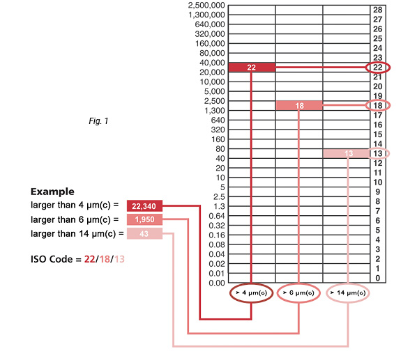
To overcome this, industries now adhere to the ISO 4406 Cleanliness Standard.
What Can I Do To Prevent System Shutdowns Caused by Contamination?
By using the ISO 4406 standard to understand fluid cleanliness for controlling contamination and wear in hydraulic systems, operators keep their systems running efficiently and operating “like-new.”
In most cases, the implementation of a cleanliness standard is a huge step in the right direction. We’ve broken it down to 7 steps for adhering to this cleanliness standard below.
Step 1: Determine the operating pressures of the system you are applying the cleanliness standards to. While determining the system’s pressure, you must keep in mind these three factors:
- The environment the system is going to be operating in
- Where a filtration solution will be installed
- The duty cycles required
Step 2: Determine the flow rates within the machine in question. The questions you need to ask are:
- What are the max and nominal flow rates that my system sees?
- Is there any type of surge or back flow present in my system?
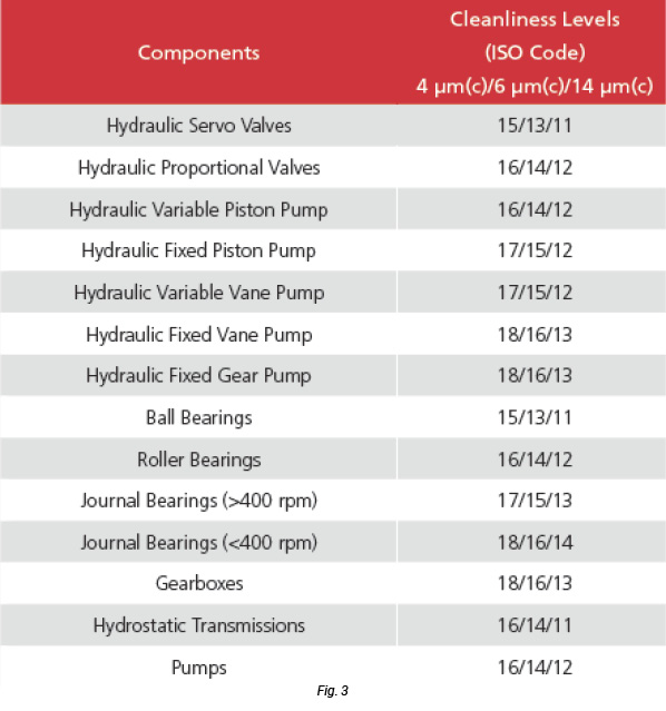
Step 3: Define your most critical component. Identify what component is used the most, and requires the cleanest ISO code reading (refer to Fig. 3).
Step 4: Use the ISO code defined in Step 3, and match it to a micron-rated filter element. There is printed literature that best recommends the micron size needed and in direct relation to the ISO code found in Step 3:
- 19/17/14 = Z10 filter media
- 18/16/13 = Z5 filter media
- 15/13/10 = Z3 filter media
Step 5: Recognize the fluid you are using. The type and viscosity of the fluid that runs in your system will help you determine the seal type and media type needed in a filtration solution, as well as the contamination type (i.e., metal, rust, water, etc.) you are experiencing the most problems with.
Step 6: Determine your maximum operating temperature. Temperature will affect the fluid viscosity. Viscosity will affect the differential pressure, which is important in selecting the proper filter housing size.
Step 7: Piece it all together. With all the information gathered from Steps 1-6, you can calculate the overall system differential pressure. Your solution should result in your clean element pressure drop being less than half of the overall bypass cracking pressure at normal operating temperature and flow.
Today’s modern equipment sure does have a lot to worry about. It’s best that OEM hydraulic designers and MRO fleet owners do not let contamination become a problem.
Share this information.
Related Posts


Sponsor

Sponsors