ISO 11727 Port Identification
Dennis Bonacorsi- Chief Engineer (retired)- Numatics, Inc., Prior Member ISO TC 131/SC 5/WG 3 Pneumatic Valves
 Proper paths are a very important requirement of everyday activities and can be a challenge, whether following a map or connecting your home entertainment system.
Correctly followed you achieve success or otherwise do not end at the proper destination or function.
The same considerations are required to connect directional control valves. To work properly, the connections to inlet and outlet ports are very important to achieve proper valve air flow function.
Connecting a valve can be a complicated task. In addition, providing information to a global market is difficult. Fluid power suppliers must develop instructions allowing a user to properly connect a multi ported directional control valve in many countries and languages. Written assembly directions we all follow everyday can make a thick document or large data file if many languages are required.
Some valves are simple with two connections, a supply and an outlet port.
Others may contain many connection ports as well as manual, air controlled or electrical control mechanisms. Ports are the means for connecting components in a system to provide proper air flow to cylinders and actuation devices. In air pressure circuits directional control valves need to be connected by proper port choice for correct attachment and actuator performance.
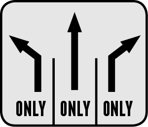
To simplify this, symbols for directional control valves were developed to replace the written word. An everyday example of a path symbol is a street intersection lane sign.
Chose the correct lane and you will find the intended path.
ISO (International Standards Organization) has fluid power standards groups TC (Technical Committees) to develop important global industrial standards using a cross section of both supplier and user members. This way a standard can be developed to provide the fluid power supplier and industrial user with a defined list of port identification.
ISO/TC131 developed a standard for port identification. ISO 11727 was developed to meet a global need. This standard identifies and provides definitions for proper numerical marking of ports on pneumatic directional control valves. These ports are supply and exhaust flow connections, actuator control connections, and pilot supply connections.
Creating port identification symbols is an advantage for both suppliers and users. ISO 11727 (port identification) was developed to assist connection means and provide proper valve function. This standard was adopted in 1999 and has greatly helped proper valve port definition and valve installation.
The difficulty of defining these flow paths in text is greatly reduced by the use of numerical definition. There are options to accommodate from 2 port to 5 port valve types. In addition there may be external pilot supply ports to provide pressure and exhaust connections used for pressure shifting of the valve’s spool.
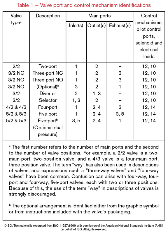
The following table 1 from ISO 11727 is a very educational comprehensive listing of valve port and control mechanisms for 2 port to 5 port valve types.
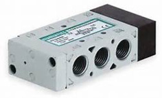 L Series 5 Ported Valve
The L series is a typical five ported valve. Valve shifting is often accomplished by using a smaller integral pilot valve. The pilot valve may use internal pressure supply from the main valve. In some cases, the pilot uses external pressure and exhaust from two additional ports located on the valve.
A symbol used for this valve illustrating port location is represented as:
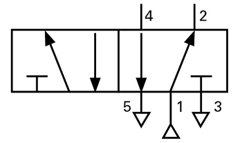
This is a 2 position valve with ports numbered from 1-5. In the right hand rectangle the ports are defined as:
- Supply pressure
- Cylinder connection Port (flow from supply pressure port through valve to cylinder)
- Exhaust from port 2 (blocked in this valve position)
- Opposite cylinder connection port (open to exhaust: port 5 in this valve position)
- Exhaust from port 4
When the valve is shifted, the left rectangle symbol represents the valve flow function using the same 5 port numerical designation. The flow pattern now becomes:
- Supply pressure
- Cylinder connection Port (open to exhaust: port 3 in this valve position)
- Exhaust from port 2
- Cylinder connection Port (flow from supply pressure port through valve to cylinder)
- Exhaust from port 4 (blocked in this valve position)
These two valve positions allow a cylinder to extend and retract by shifting this 2 position valve.
ISO 11727 uses such symbols as shown here in addition to many other valve option symbols to represent valve function in a non-text manner. These symbols are typically printed on labels on valves and port numbers are marked on the valve body adjacent to the port to provide a convenient representation of function.
This standard allowed the use of these symbols greatly simplifying valve definition and understanding.
Other ISO standards work in conjunction with ISO 11727 to help define valve action.
ISO 5598, Fluid power systems and components — Vocabulary
ISO 5599-1, ISO 5599-2 and ISO 5599-3 — Port number definition
The NFPA Standards Locator: npfa.com/standardization/findstandard.aspx
“Why Standardize?” npfa.com/standardization/whystandardize.aspx
Interested in Joining a TAG Committee? npfa.com/standardization/standardscommittee.aspx
Learn more about NFPA and ISO standards at www.nfpa.com/standards
Share this information.
Related Posts
Choosing the Right Fluid Power Sealing Solutions for Construction Equipment
Three Associations Connecting the Fluid Power Industry

Reliable Pumps Critical to Carrier Launch Systems

Predictive Intelligence and Monitoring Keeps Pneumatic Components Running

The IFPS Certification Challenge
Compressed Air Efficiency: 5 Uses of Storage
Sponsor

Sponsors