It’s Over: Breaking with Valve Position Tradition
By Jerry Hines, Key Account Manager, Pepperl+Fuchs.
Tank farms play a critical role in the oil and gas industry. They serve as way stations for crude oil before it is needed at the refinery, finished product before it is needed by the end user, and different products before mixing. These facilities are also home to large networks of pipes and therefore large numbers of valves.
Valves are essential for controlling the flow of liquid petroleum into a tank-farm’s pipe networks and into and out of its tanks. Gate and expanding plug valves have been the primary valves in tank farms for decades; however, check valves, ball valves, and butterfly valves have also been introduced to provide backflow protection and emergency shutdown capabilities.
With networks of different types of valves as far as the eye can see, monitoring valve position manually is nearly impossible. Fortunately, large-scale automation of these systems has created safer and more streamlined valve monitoring, preventing valve lineup errors and subsequent product mixing, overflow, fire, or explosion. Devices that ensure clear and consistent indication of valve position are a critical component for reliable monitoring from the control room (figure 1).

Traditional detection
Valve position sensors are mounted on the actuators for both rotary-actuated valves and linear-actuated valves. Sensors transmit valve information directly to the control room using a wired or wireless connection. The connection between the sensor and the control room gives operating personnel feedback on valve position in real time, indicating when it is safe to start transferring product. This eliminates human error and improves the reliability of valve operations.
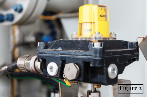
The sensors are available in two basic switching options: mechanical and noncontact. Traditional mechanical valve position feedback systems depend on cams, mechanical linkages, and other physical components to detect valve position. Mechanical position sensors are mounted on the extended shaft of valve actuators and often come in large switchboxes (figure 2). The switching elements must make physical contact with a target to actuate. Once the target is detected, mechanical systems send discrete electrical signals to the control center to indicate valve position.
While traditional valve position solutions are often more affordable, they have multiple moving parts that are subject to wear and corrosion. Because of this, the systems often come in enclosures designed to protect the internal switching elements from direct exposure to the environment. Even so, dirt and moisture still enter many of these enclosures because they are not designed to completely shield the mechanical components inside. This means they do not provide lasting protection against gases, vapors, and atmospheres, which leads to corroded contacts and electrical components.
In these often harsh conditions, data and power cables are subject to physical damage. In particular, severed or compromised cables can lead to unreliable readings of the valve’s position. Traditional approaches often involve additional circuitry to monitor these systems for situations in which the switch becomes unresponsive or the leads are damaged.
Although still popular, traditional solutions are not ideal for the rugged environments in the downstream oil industry. Constant exposure to the elements, especially in locations near the ocean, decrease the reliability of mechanical feedback systems over time, which leads to detection errors and device failure.
This, coupled with frequent replacement costs, does not provide the reliability that tank-farm operators are looking for.
Breaking with tradition
Noncontact solutions, on the other hand, can be directly mounted on the actuator with no additional component considerations. Since they rely on inductive sensors, they are resistant to mechanical and environmental influences. This ensures convenient, wear-free operation, making the sensor a durable, cost-effective, and reliable alternative to traditional mechanical models.
Inductive sensors are actuated by metallic targets; the influence of the actuator on an LC resonant circuit is critical to this. When the actuator changes its inductance, the frequency of the resonant circuit also changes. The sensor electronics generate an output after detecting that the actuator has entered the magnetic field of the resonant circuit.
Inductive noncontact solutions are designed for most applications and the challenges they present. Because noncontact sensors do not have moving components, the electronics can be hermetically sealed, making them ideal for indoor, outdoor, extreme use, and hazardous-area applications. Being sealed, inductive sensors are also resistant to dirt, dust, oil, moisture, and chemicals.
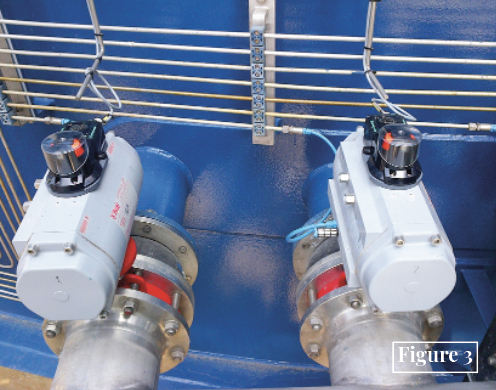
One specific application where this benefit was recognized by a Pepperl+Fuchs customer involved a salt-tank terminal in the Netherlands. Traditional mechanical systems in enclosures had been used for many years but were failing constantly due to condensation and water ingress. The customer implemented a pilot project using inductive sensors (figure 3), and the moisture issues were no longer a factor. Switching from the traditional approach led to a reduction in downtime, maintenance cost, and error almost immediately.
The benefit of electronic systems can be leveraged in many other ways, further differentiating them from mechanical systems. Unlike mechanical systems, monitoring for lead breakage or short-circuit conditions is inherently simple. Most contactless sensors offer a status monitor that alerts the user of these potentially dangerous conditions.
In the past, electronic sensors were often viewed as a liability when connected directly to a control-system input card. The continuous power needed to keep the sensors active would occasionally cause a “false trip” due to leakage current being detected by the input card. With advancements in electronic technology, many inductive sensors can now cross that concern off the list. Sensors with low-leakage current technology now offer off-state current leakage of <0.2mA, which is well below the threshold of detection by an input card.
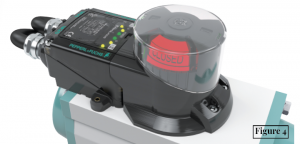 Within the family of inductive position feedback sensors, dual sensing solutions provide an extra advantage. They combine two inductive sensors in one housing and provide separate feedback signals for open/closed position (figure 4).
With a wide variety of electronic outputs (i.e., 3-wire PNP, 2-wire DC, and AS-i) and direct mount “targets,” the dual-sensor package offers considerable flexibility when configuring position feedback for any application. These double sensors offer a wide range of connectivity options integrated into the sensor package. For example, integrated terminal compartments are a popular option because they allow easy wiring installation, commissioning, and troubleshooting.
Open solutions
Especially in environments with large numbers of valves, high visibility and easy installation are critical. Open-solution inductive valve position sensors were designed for these applications, offering more flexibility than their traditional counterparts. Valve position sensors that follow this concept can be mounted directly onto automated and manual valves. Drives standardized to VDI/VDE 3845 and NAMUR mounting holes make this possible because they eliminate the need for mounting brackets. Once installed, two stainless steel targets mounted on an activator, or “puck,” activate the sensor. Combined LEDs allow tank-farm workers to check valve status from the field, ensuring clear indication of valve position at every level (figure 5). Since the sensor is mounted directly on the valve, wiring can be routed through the sensor so that no separate cable needs to be run to the field.

Although open valve position solutions are often installed on valves that are remotely operated, they can also be used to indicate the position of manual valves (see figure 4). Position sensors can be directly mounted to valves that regulate shutoff or pipeline flow, like those found in tank terminals. When a hand wheel is turned to open or close a valve, the control room is alerted and an incorporated indicator signals the position of the valve. This provides a new level of certainty from the control room all the way to the field.
Inductive valve position sensors bring a new level of reliability to tank-farm applications. With clear position indication, ruggedized components, and a standardized mounting, they are designed to operate in any environment. Noncontact valve position sensors ensure that natural gas liquids are transferred to storage and terminal operations safely and efficiently, which saves money and time for tank farms and their employees.
Share this information.
Related Posts


Sponsor

Sponsors