Keeping Cool with Hydraulic Case Drains
 By Tommy Williams, AKG Thermal Systems
Maintaining a proper oil temperature in a hydraulic system is essential for successful operation. High fluid temperatures can damage components and significantly alter the way the system performs, resulting in costly repairs and downtime.
Hot oil increases internal leakage in pumps and motors, causing the machine to operate more slowly. O-rings also harden at higher temperatures, leading to more leaks in the system.
Further, hydraulic fluid temperatures above 180°F (82°C) may damage seal compounds and accelerate oil degradation. Operators should avoid running a hydraulic system at temperatures above 180°F (82°C). Every 18-degree increase in temperature above 140°F cuts the oil life in half. Systems that operate at high temperatures can produce sludge and varnish, which result in damage to the hydraulic system and reduce efficiencies.
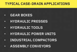
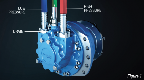
Pressure-compensating piston pumps are commonly used in industrial hydraulic systems. Tolerances allow for a small amount of oil to bypass, generating heat that is piped back to the reservoir through the case-drain line. There are many other reasons for heat generation in hydraulic components and systems; the inefficiency of the pump, friction in the pipes, joints, line fittings, and so on, are the major contributors to heat generation. The tolerances inside pumps and valves are generally in the ten-thousandths of an inch. These tolerances permit a small amount of oil to continuously bypass the internal components, causing the fluid temperature to rise.
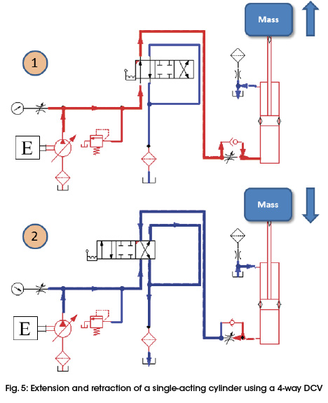
Flow controls, proportional valves, and servo valves control the oil’s flow rate by causing a pressure loss as oil flows through the valves. This means that higher pressure exists at the valve’s inlet port than at its outlet port. Anytime oil flows from higher pressure to a lower pressure, it generates heat that is absorbed in the oil.
Gear pumps and motors generally do not have a case drain, but they do have internal leakage, which, by design, usually accumulates in a small cavity just before the shaft seal. Air-cooled compact heat exchangers can be used to address the heat in this area.
 The case-drain line’s average flow rate is 1% to 3% of the maximum pump flow. Anyone can permanently install a flow meter in the case-drain line to monitor flow rates.
When a pump or motor is worn or damaged, internal leakage increases, and therefore the flow available to do useful work decreases. This means the hydraulic efficiency decreases and results in additional heat generation. Implementing a case-drain cooler can assist with maintaining a viscosity range at which your machinery operates most efficiently. System checks should be performed regularly to determine the amount of bypassing oil. The pump should be changed when the oil flow reaches 10% of the pump volume.
By introducing cooling into the system, efficiencies increase, resulting in less power consumption. In some cases, high oil temperatures that are reflected back to the drive motor lead to wasted electricity by forcing the drive motor to pull more current to operate the system.
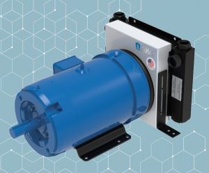
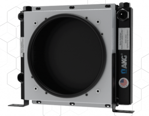
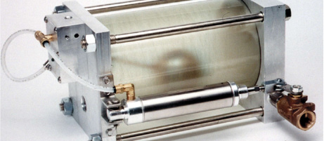
Case-drain coolers are ideal for applications requiring minimal cooling. These coolers offer minimal mounting to reduce installation time, typically with horizontal and vertical options. The cooler mounts behind an existing TEFC motor, using the electric-motor fan airflow. Cooling flow is obtained from the case drain of the hydraulic machine and is then guided to the integrated electrical machine. Pressure losses in the electrical machine can be seen as negligible. The outgoing flow moves by gravity as long as the outlet and inlet ports are of adequate dimensions.
To select the best air oil cooler, provide as much information about the application as possible, including oil heat load in Btu/h or hp, oil flow rate in gpm, maximum inlet oil, and maximum ambient air temperatures during operation.
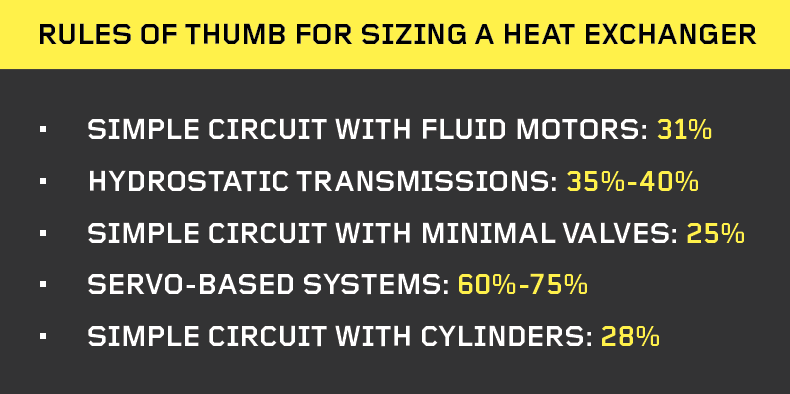
If the required heat dissipation is unknown, it can be estimated that 20% to 30% of the installed horsepower will be converted into heat load. Heat exchangers can be used to remove the excess heat in a hydraulic system. The implementation of a heat exchanger has many variables that need to be taken into account.
The heat exchanger and reservoir should be sized when a system is initially designed to remove the generated heat. The reservoir allows some of the heat to dissipate through the walls to the atmosphere. The heat exchangers should be sized to remove the balance of the heat. The heat exchanger needs to be maintained to ensure excess heat is removed. If an air-type heat exchanger is used, the cooler fins should be cleaned regularly. A degreaser may be necessary to clean the fins.
To ensure profitable and efficient success in a manufacturing operation, maintaining a proper oil temperature in all hydraulic systems is essential. High hydraulic-fluid temperatures can damage system components and significantly alter the way a hydraulic system performs, resulting in costly repairs and downtime.
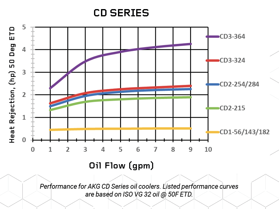
AKG Case-Drain Series
The AKG Thermal Systems CD Series is designed to fit in tight spaces and conveniently mounts onto a power unit with limited envelope space. The narrow profile conditions and cools for a wide array of applications.
The AKG tube fin design offers more significant cooling and does not require a protective guard. This cooling setup is compact, low cost, and low flow with minimal heat removal.
CD Series features:
- tube and fin aluminum design,
- coolers mount onto the rear of TEFC frame motors,
- competitive pricing and assembles from stock,
- premium-quality lightweight construction.
For more information, visit www.akgts.com.
Share this information.
Related Posts

Hydraulic Products and the Replacement Market
Don’t Drain Your Profits: Remove Compressed Air Condensate Efficiently
Cam Lobe Radial Piston Motors: Compact, Capable, Constant

Get Smart: Digitized Vacuum Ejector Bolsters Predictive Maintenance

The Unvarnished Truth: Contamination Control Makes Servo Valves Click
Motion Control of a Single Actuator Against a Resistive Load
One thought on “Keeping Cool with Hydraulic Case Drains”
Leave a Reply
Sponsor

Sponsors
Nice blog regarding Coolness with Hydraulic Case Drains. Warkin Equipments is also dealing with the same manufacturing process.