Locking Protection is Key to Hydraulic System Safety
By David Bickford, Principal Engineer, Innovation and Performance Excellence, York Precision Machining & Hydraulics LLC
When load-holding equipment fails, the results can be catastrophic and can include personal injury, death, property damage, investigations, fines, lawsuits, business-flow disruptions, and bad publicity with customers and the public.
There are many options for hydraulic load-holding safety equipment available for use in design selection and application. In this article, we will also discuss the various aspects of different safety options and considerations when designing your hydraulic system. Our goal is to inform the industry of legacy, low-technology options and other higher technology options to meet increasing safety and performance requirements being imposed by industry changes, liability avoidance, or regulatory mandates.
Hydraulic circuits contain load-holding valves (LHV), also sometimes referred to as counterbalance valves. LHVs are a legacy means used to hold a hydraulic system applied load in place and control its rate of motion. These valves are common safety components of load-carrying equipment and typically a staple of hydraulic safety and control design. When they operate as expected, they improve the safety and control of a hydraulic circuit. Many equipment operators and companies do not want to rest their safety on only the counterbalance valves – and for good reason. Used alone, these items have limits to the measure of safety they provide. Any failure or sticking of the valve or components, failure of parallel check valves, hydraulic hoses, and fittings, or even seals in cylinders can cause load movement or drift if LHVs are the only means of safety. LHVs automatically regulate the extension and retraction speed of loads and holding equipment and help control and steady the system. Because of this smoothing out of pressure for speed and preventing pressure shock, typically LHVs cannot be eliminated from circuits, so they must be supplemented for higher-level safety design.
Options for a fail-safe locking device
There are various options for supplemental mechanical locking. They range from locking pin basic designs that are locked either by automated or manual methods, up to solutions reflecting the highest technology cylinder-integrated, power-removed, spontaneous self-locking mechanisms. The appropriate mechanical locking mechanism design options are typically driven by power needs, space envelope, operating pressure, operating environment, and whether it is desirable for automatic lock or operator manual locking. These parameters set the stage for choosing options.
First levels of locking protection consist of automated or manual locking assemblies such as collars that will use pins, or other clamping options like spring pressure that locks a cylinder either at extended, retracted, or both positions. These are easy options to find on the market and serve to lock out at the travel extremes of the rod. They do not provide instant locking at any point of travel between the two extremes, and they require additional automation and components that, if not maintained, could fail, wear, and result in degradation to the system. Their application is limited by these considerations, but they can serve a distinct purpose when safety can be met in these means.
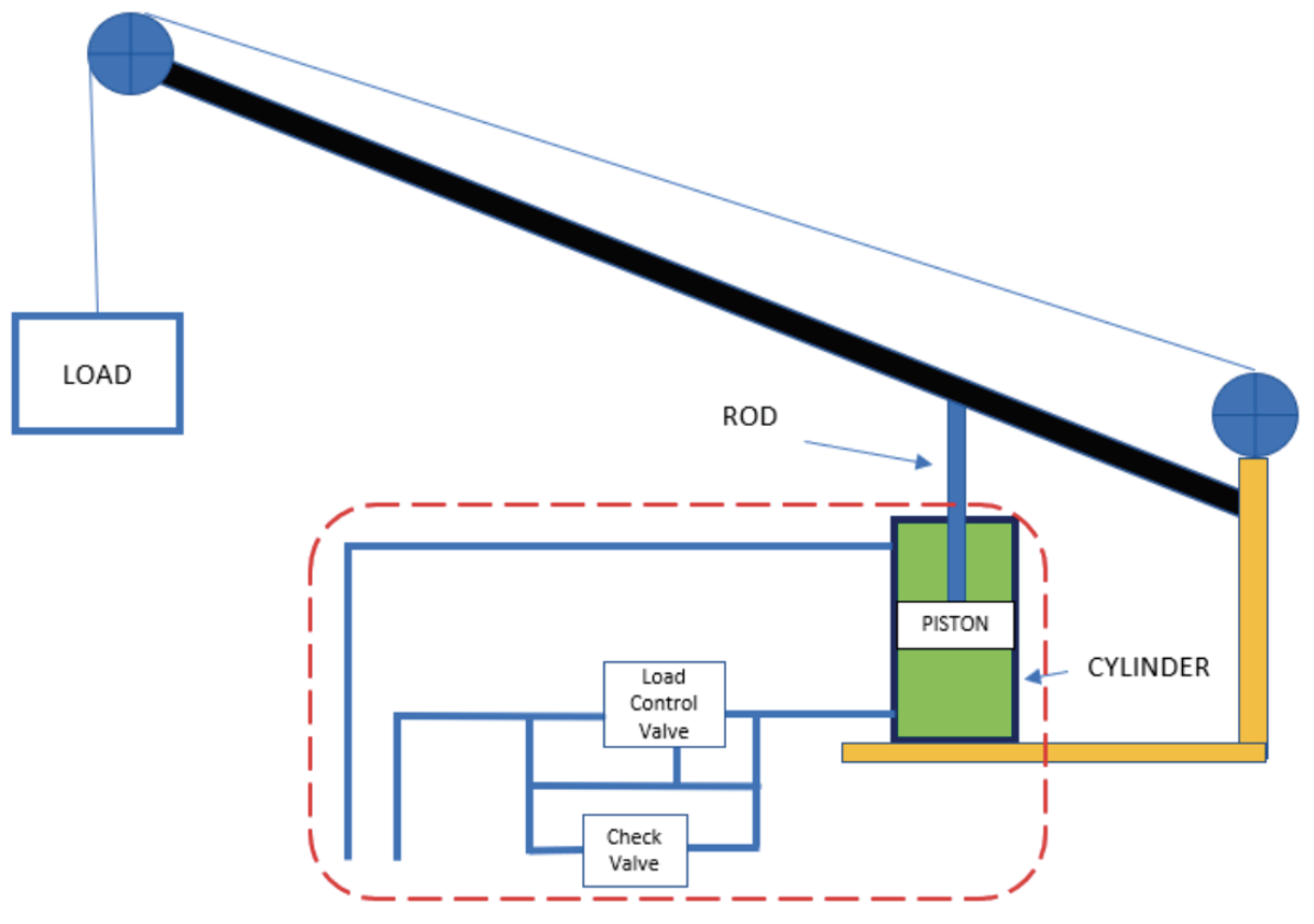
Top: A crane system main boom cylinder using only an LHV for safety protection. The system depends on the components within the dashed line to lock a load in place or prevent drift. The failure of any of these components could be disastrous.
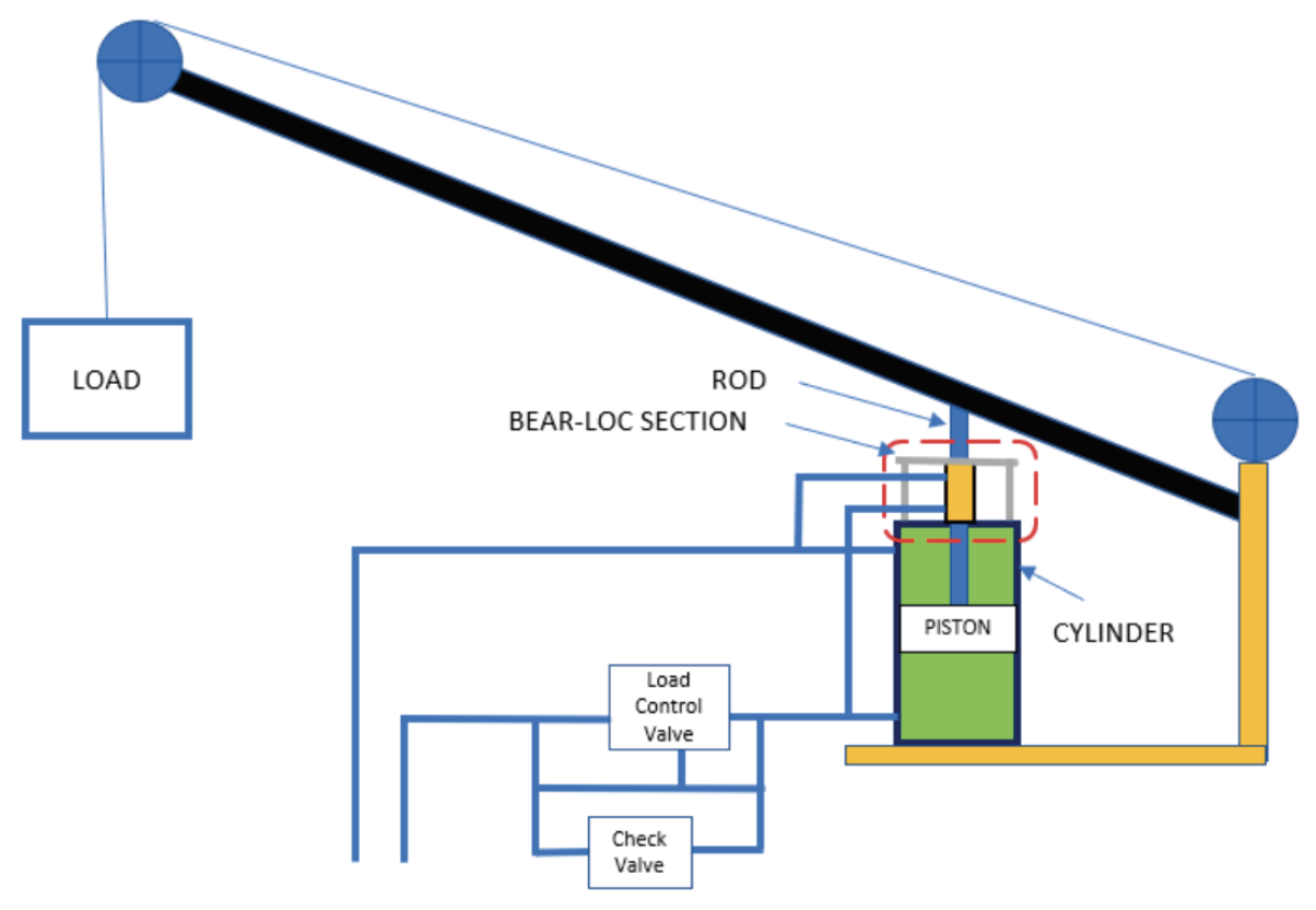
Bottom: A crane using a Bear-Loc, the only component that load safety depends on. Bear-Loc takes the hydraulic circuit and power out of the equation for load safety and lockout. It also retains the load, even if the hydraulic fluid bled out or seals were damaged or lost.
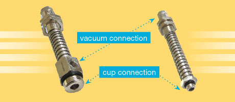
Supplementing these end-of-travel locks by adding an additional lock that can be engaged through the length of travel provides an additional level of protection. These locks are typically spring loaded or contain another perpendicular and smaller hydraulic or pneumatic cylinder that is placed as a collar or an installable “head” on top of the cylinder rod end. The lock will fit around and actuate to clamp against the rod and lock it at points in travel. The systems tend to be limited to cylinder pressures of up to 2,500 psi and therefore limit their ability to be used in higher load applications or higher operating pressures. These solutions are inexpensive and common and can be effective with limitations. The assemblies are intended to prevent catastrophic failure. With some designs, they require removing the load and the cylinder in a specific direction to release the lock. These designs could have limited repeatability and may cause sacrificial degradation to the cylinder rod and limit continued use after an emergency safety lock is initiated. Assess products you examine for this characteristic, especially when an unlock and instant resumption of cylinder operation would be desirable. Reliability of the design and its ability to continue in service without maintenance burdens are critical considerations.
Integrated, power-removed, interference locking units are options for the highest level of safety. These designs are hydraulic cylinders with self-contained locking assemblies that can meet the highest load demand, operating pressures and instant stop, rugged durability, and no drift. They eliminate any other component in the system that could cause a failure, including the cylinder fluid and seals. They narrow the safety dependency down to their integrated locking feature and the rod itself. These systems have the lowest count of possible component fail points and possible failure modes in the design that could cause an uncontrolled load movement or failure. These designs are the most robust locking options in strength. They have infinite-position locking, zero backlash, and high stiffness when required. They can have instant lock or unlock and facilitate repetitive life-cycle use with no sacrificial degradation of system components. As a positive lock, the system instantly locks when hydraulic pressure is removed, averting the risk caused by accidental pressure loss by whatever cause.
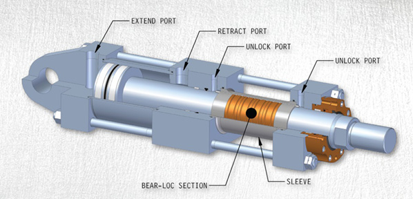
One locking system that meets all these criteria is the Bear-Loc, a design in which the cylinder has a supplementary section attached to the cylinder end. The Bear‑Loc consists of a sleeve that provides an interference clamping/frictional locking system that locks the rod in any phase of the stroke when hydraulic pressure is removed. The sleeve has a fluid pressure lock-and-unlock port integrated into the hydraulic circuit. The design is based on the principle of elastic expansion of metal under pressure. When hydraulic pressure is applied, the sleeve expands radially, removing the interference fit of the rod inside the sleeve and creating enough clearance for the rod to be stroked with virtually no resistance. Removing the hydraulic pressure in any manner automatically causes the sleeve to instantly re-engage in its interference fit with the rod and clamp back down on the rod. The sleeve is lined with a material that prevents rod plating degradation for the life cycle of the rod.
This type of system is versatile in the ability to instantly lock or unlock simply by the application or removal of pressure; it does not require removal of load or depressurization to unlock. These systems are superior in safety due to their ability to be integrated onto a cylinder. They can be used in most operating environments including underwater locations or other high-stress environments where other system components could be degraded and fail, yet the load control is maintained with no safety risk. Because movement takes place while “unlocked,” there is very little wear, and so the Bear-Loc system is known to last for years, even decades, when used according to the manufacturer’s specifications. These systems have very tight tolerance and are typically customized to meet performance needs. They can operate at higher loads up to 4 million pounds and can be made for rod diameters of 1 to 25 inches.
The locking power of these systems is dependent on several factors, chiefly operating pressure, rod diameter, and available sleeve length. The force to cause the radial elastic expansion of the metal sleeve does require operating pressures from 2,000 to 5,000 psi, but it is these higher pressures that result in a fail-proof design without the need for supplementary subsystems or circuitry.
These features ensure that a hydraulic system with a Bear-Loc does not depend on valves, moving parts, or other components to obtain its positive mechanical lock. The Bear-Loc can work solo or in conjunction with existing equipment to keep people, equipment, and projects safe and productive.
A common question is whether the locking assemblies discussed above are also rod brakes to slow or bring them to a stopped position as a regular part of operation. The Bear-Loc may be used in an emergency for braking but not routinely. It is important to note that this article does not discuss cylinder or rod brakes; it discusses locking assemblies, i.e., features of a system that stop and prevent drift or motion and are applied instantaneously and triggered by something unsafe in the system. Braking is a separate functional purpose of load control and can be met with the use of an LCV.
Productivity and safety
Many forms of equipment use mechanical locking in their hydraulic systems, including construction or mining equipment such as cranes, load handling equipment such as fork-lifts and stock pickers, aerial work platforms such as boom trucks, test equipment, weapon systems such as missile launchers, manufacturing equipment such as industrial presses, oil drilling rigs, and amusement park rides.
Design for safety can be a necessity, but sometimes safety implements can reduce productivity, either by design or process steps they introduce that add time to the completion of job tasks. Manual locking methods require an operator’s time and reduce productivity. Even automated tasks can impact productivity. As you consider your design, or lock-out, tag-out considerations, you will find that there can be a balance in which your safety implement does not affect your productivity, and in some ways can even enhance your productivity in other process steps.
An example of this is a hydraulic molding press. The press must be locked out at certain points when the operator may have to be near or under the press for other tasks. The system requires a locking capability for this. The press brings two molds together so they can be filled with a cast or injection molded product. When the mold halves come together, if pressure is not sustained or a nonslip lock is not used, there can be drift, in which a slight opening between the molds consumes extra material, requiring subsequent processing and added cost to remove additional flash around the part. In this situation, more advanced locking features can give the manufacturer a benefit that enhances productivity. A Bear-Loc system would provide the necessary safety, but also when the press brings the molds together and removes pressure, the rod does not drift and the molds stay compressed, preventing flash around the part being formed. This is just one example of the added benefit to using some of the more advanced locking systems rather than less-expensive systems. The higher priced system helps pay for itself in enhanced productivity during operation.
Making design decisions involves trade-offs associated with requirements for performance, safety, cost, schedule, reliability, and the life cycle cost of the system. There are numerous considerations as safety is designed into hydraulic systems to meet these project needs. While performance has a price tag, it can also create peace of mind, consistency of operations, and reduce waste. As you design or modify your hydraulic system, be certain to assess the capabilities of any system or component you consider.
For more information, visit https://yorkpmh.com/products/bear-loc/.
Share this information.
Related Posts


Sponsor

Sponsors