Motion Control of a Single Actuator Against a Resistive Load
This series of articles covers the basic safety and energy-saving requirements of a hydraulic system. This third installment presents ideas for motion control of a single hydraulic actuator against resistive and running load.
Motion Control of a Single Actuator
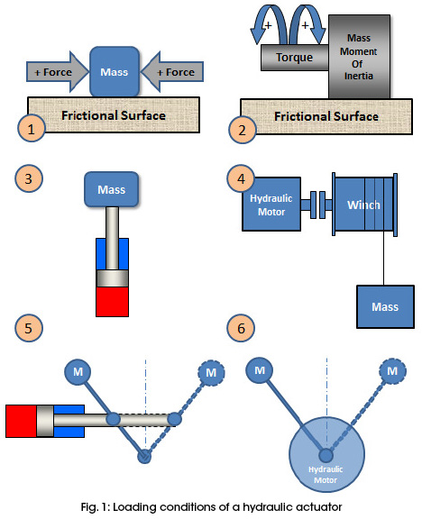
Depending on the sign (positive or negative) of the load, as shown in Fig. 1, a hydraulic actuator may be subjected to various loading conditions as follows:
- Positive (resistive) load: The load resists the motion of the actuator in both directions. Linear and rotational positive loads are shown in the figure as applications 1 and 2.
- Combined load: The load resists the motion of the actuator in one direction and becomes negative (assisted) load in the other direction. Negative load is also referred to as “over-running load.” Linear and rotational combined loads are shown in the figure as applications 3 and 4.
- Over-Center Load: The load can switch its sign in the same direction. Linear and rotational over-centering loads are shown in the figure as applications 5 and 6.
Motion Control of a Single Actuator Against a Resistive Load
Motion Control of a Single-Acting Cylinder
The challenge a system designer faces is that the same application can be done multiple ways. A single-acting cylinder could be of a spring-return type or a load-return type. Therefore, in order to avoid overrunning the cylinder and a surge flow back in the return stroke, some sort of overrunning control must be used.
A single-acting cylinder could be driven by different types of directional-control valves (DCV). The selected DCV could be normally open or normally closed.
The following section presents several circuits to control a single-acting cylinder to achieve specific logics.
Using a 2-Way Directional Control Valve
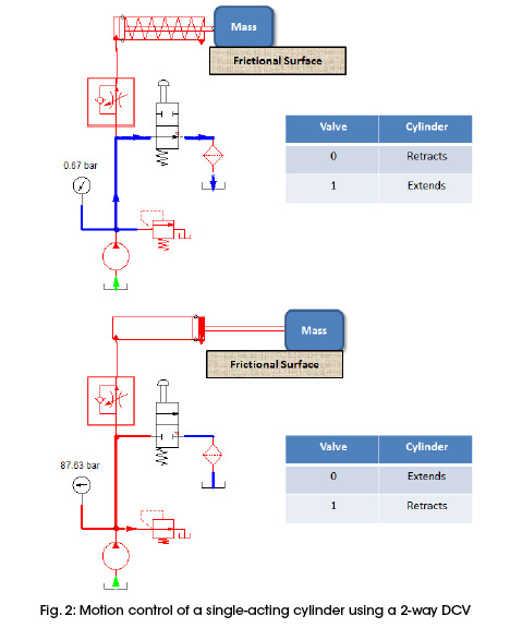
Fig. 2 shows a spring-return cylinder. Because the spring applies a decreasing force during retracting the cylinder, a pressure-compensated flow-control valve is used to return the cylinder at constant speed. The figure shows a 2-way, 2-position DCV to extend the cylinder. The valve is placed in parallel with the line to the cylinder.
The DCV could be normally open or normally closed to achieve the corresponding logic shown in the associated truth tables in Fig. 2. If a normally closed valve is used, a pressure-compensated pump is recommended to improve the efficiency of the operation.
Using a 3-Way Directional Control Valve
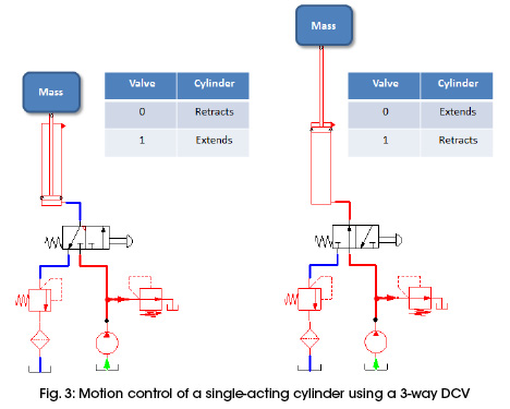
Fig. 3 shows a load-return cylinder. Because the load is constant during retracting the cylinder, a simple counterbalance valve is used to return the cylinder at constant speed. The figure shows a 3-way, 2-position DCV to extend the cylinder. The valve is placed in series with the cylinder.
The DCV could be normally open or normally closed to achieve the corresponding logic shown in the associated truth tables in Fig. 3. If a normally closed valve is used, a pressure-compensated pump is recommended to improve the efficiency of the operation.
Using a 4-Way Directional Valve
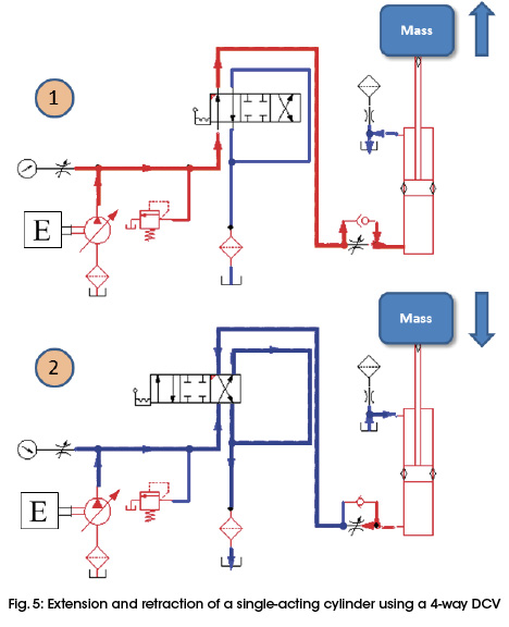
It is unusual, but still feasible, to use a 4-way DCV to drive a single-acting cylinder. In the circuit shown in Fig. 4, an engine is used to drive a fixed-displacement pump. A snubber device is used to protect the pressure gauge against the pressure spikes and to stabilize the pressure reading. The empty side of the cylinder is vented through a breather filter to prevent dust from getting into the cylinder during the retraction stroke. Position “a” is used to lift the load, and position “b” is used to lower the load. A throttle-check valve is used to control the lowering speed of the load.
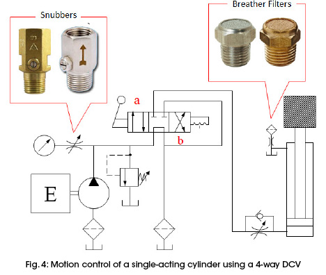
Fig. 5 shows the operating conditions of the circuit: Part 1 shows lifting the loads, and Part 2 shows lowering the load and unloading the pump.
This chapter excerpt is taken from the book, Introduction to Hydraulics for Industry Professionals: Hydraulic Systems, Volume 1, 1st edition. Dr. Medhat Khalil, Ph.D., CFPHS, CFPAI, is director of professional education and research development, Applied Technology Center, at the Milwaukee School of Engineering (MSOE). This book is distributed for free to MSOE seminar attendees and sold separately at www.compudraulic.com (10% discount code FPJ2016 for Fluid Power Journal readers).
Share this information.
Related Posts

New Sealing Technology and Materials for More Efficient and Sustainable Heavy-Duty Equipment

Non-Contact Transport Delicately Handles Chocolate-Coated Cookies

Upskilling in Fluid Power

2016 IFPS Spring Meeting

Transforming Our Thinking: What in the World is a VDT?

Meet the Staff of the Fluid Power Journal
Sponsor

Sponsors