Size is not important … Threat is! Improving Fluid Power System Reliability
PART ONE
Jobey Marlowe
Vice President of Technology Magnom Corporation
INTRODUCTION
This paper explains how the strategic deployment of a simple technology within critical fluid power systems, brings about very specific benefits that have previously not been possible. Using detailed and documented evidence from independent sources as well as end user real life system experiences, the paper will validate the proposition and the technology.
HISTORICAL PROBLEMS IN FLUID SYSTEMS
CONVENTIONAL FILTRATION…A HISTORICAL LEGACY
Sieve/barrier or interception type of filtration, whether it is 5 micron absolute filter or a 200 mesh screen, all work primarily by being size discriminating to contaminants & particles. This type of element is designed to trap particles larger than the pores (voids) in the media itself. One result is that particles smaller than these pores tend to pass straight through the media unimpeded. For the purposes of this paper, this is defined as ‘discrimination by size’.
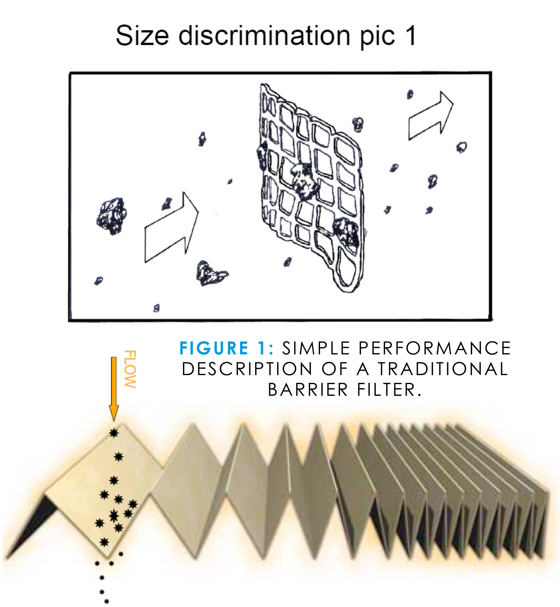 Figure 1 provides a graphical representation of the performance of a traditional barrier filter (conventional filtration) in terms of particulate size.
Within the fluid power industry and many other industries that utilize conventional filtration techniques and technologies there are some assumptions & practices that have been generally passed around for decades. Most of these assumptions deal with the performance of the conventional filter itself. Specifically that filtration performance within a real life system at the end user level, mirrors the performance of the same filtration inside a controlled laboratory environment. The important (incorrect) assumption in this case is that the two locations are treated as identical and mutually relevant. The standards generally portrayed important performance characteristics of a conventional filter are usually Beta Ratios and ISO Tests.
What started as a good idea, namely to provide a generic baseline to compare one filter element or screen against another, has evolved into a generally accepted measurement of system efficiency. Conventional filters have been continuously developed and redeveloped over the years to meet these standards (test parameters). The issue at hand is that in general, the tests are not truly representative of the real life environment in which these filters are applied.
ISO TEST BASICS
Within the laboratory environment, filter ISO testing is typically based on a percentage of contaminants captured under a steady state (constant) flow rate. The contaminant introduced is a standard ‘dust’ as defined within the ISO standard. The first issue to consider are the real life characteristics in hydraulic & fluid power systems.
 ISO testing was developed in an attempt to quantify the performance characteristics of a filter on a hydraulic system on a power unit, under steady state operating conditions. This is important because a non-varying flow rate signifies that no valves, actuators, variable volume pumps or external loads are ever imparted on the hydraulic system.
Any end-user or designer of fluid power equipment knows that a real-life hydraulic system is anything but constant flow. Almost all industrial power units and mobile systems undergo massive variations in demand and flow.
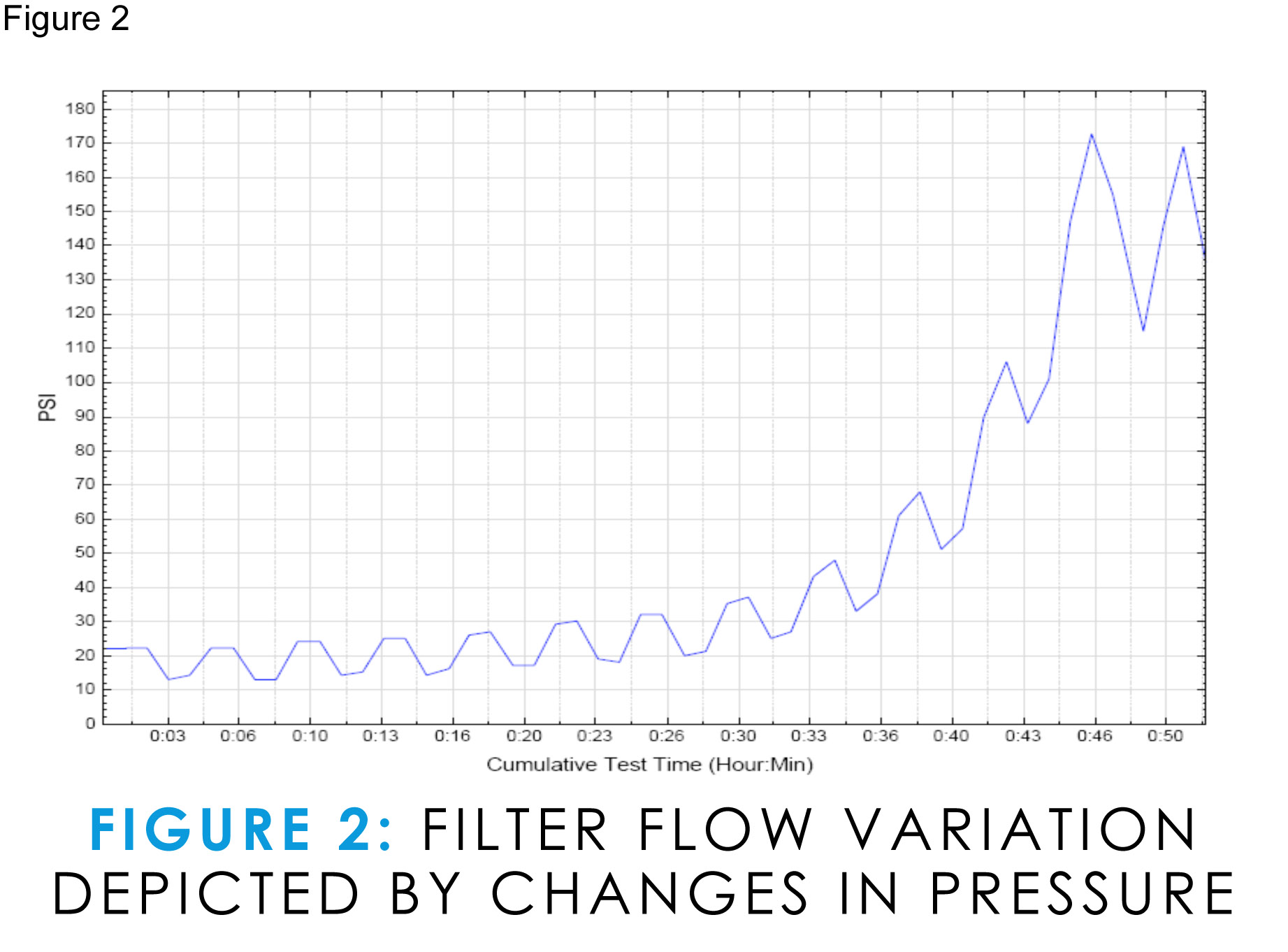
This variation in flow rate has a remarkable effect on the performance of a conventional 10 micron absolute filter element (industry typical element). When the exact same filter elements are tested, one in a standard steady-state ISO test and another in the same test except with variable flow rates, the collection & retention efficiencies of the filter are affected dramatically. Figure 2 shows changes in flow rate as measured by changes in pressure across the element. The flow rate is varied approximately 30% every two minutes over the length of the test. This test is known as Dynamic Filter Efficiency (DFE).
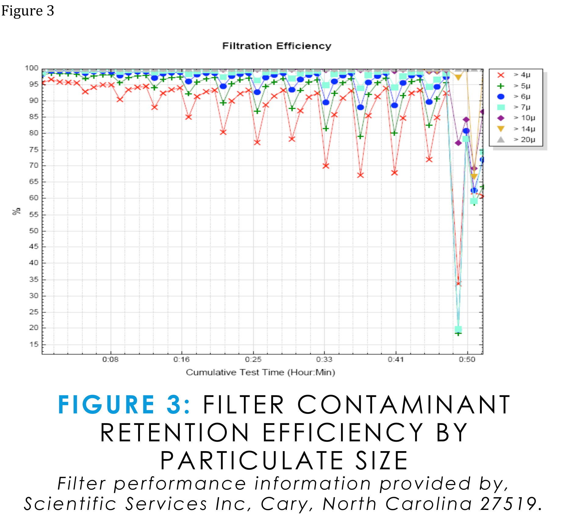 At the 0:49 minute mark the filter again experiences a change in flow rate of approximately 30%. More specifically, this represents a reduction in flow rate as a real life system may experience with just the opening or closing of a valve. Figure 3 shows the effect of the change in flow rate on the filter elements ability to retain previously captured contaminant. The 0:49 minute mark in Figure 3 shows retention percentages as low as 18%. This is equivalent to the element emitting large and concentrated clouds of contaminant downstream of the filter and headlong into the valves, cylinders and pumps.
If the flow is then varied from minimum to maximum (as in a mobile system) then the affect on ‘filtration efficiency’ & ‘contaminant retention by the filter’ is even more dramatic. This is one reason why for years hydraulic engineers and customers have been puzzled as to why seemingly clean (as far as the ISO rating goes) pieces of equipment fail to perform or fail on the jobsite without any apparent change in conditions.
LIMITATIONS WHEN SPECIFYING CONVENTIONAL FILTERS
Conventional filters require compromises and special considerations when being specified & fitted to fluid systems. The hydraulics engineer must take into consideration system conditions such as… flow direction, flow restriction, typical flow rates, pressure differential and by-pass requirements.
Let us not forget one of the biggest assumptions for system designers is that customers actually change the filter elements when the element reaches saturation. However, more often than generally acknowledged, this is not the case. This is especially true of mobile hydraulic equipment out on the jobsite. Often a filter goes unchanged because the job is behind schedule and the equipment is used right through the specified service interval.
All of the considerations briefly outlined above are taken in account by system designers when installing a conventional filter and yet the greatest threat to fluid power systems has not yet been addressed. The objective of this paper is not to make the case that conventional filters are not necessary or that they are worse than no filter at all. The objective is for the reader at this point in the paper to understand that conventional filters do have limitations in real life environments, and that viable complimentary solutions are available.
THE GREATEST THREAT TO FLUID POWER SYSTEMS
WHAT CAUSES FAILURES IN FLUID POWER SYSTEMS?
Apart from the build-up of excessive heat in fluid power systems, failures as a result of contamination are at the very top of any hydraulic engineers list of potential causes. More specifically, contaminants as hard as or harder than the material makeup of the system components themselves is the root cause of excessive wear. Essentially pieces of the system itself, in the form of contaminant come from one of the following three sources:
- Built in during manufacture,
- Generated during start up & break in,
- Generated as part of general wear and tear over time and/or ingested.
80-90% of the products manufactured world-wide are manufactured from Carbon Steel. Therefore it will be no surprise that the vast majority of contamination built into a product/system at the point of manufacture is steel or iron.
During start up and break in, some of the components that are breaking in and being “worn in” will be steel on steel. A large portion of steel (ferrous) contaminant becomes suspended in fluids during this period. This is the reason fluid systems, from the engine and transmission in an automobile to the hydraulic system of an ‘off highway’ piece of mobile equipment, have their oil and filter changed as part of the break in procedure. This is a clear attempt to prevent premature wear, damage and failure caused by ferrous contaminant circulating in the fluid.
During the life cycle of any fluid power system ferrous contaminants are present and are the catalyst for the “chain reaction of wear” (and cause of imminent catastrophic failure) . The “chain reaction of wear” is described as a few particles, circulating in the system and generating additional particles and these additional particles along with the original particles generating even more particles at an exponential rate. This condition is exactly why oil analysis laboratories world wide use ferrography when performing oil sample testing as part of a trend analysis program. The laboratories understand that it is the ferrous particles that are the greatest threat to a real life hydraulic system in the field and the mere presence of these particles could spell trouble in the form of ‘decreased’ performance and ‘increased’ maintenance costs.