Pascal’s Law and Counterbalance Valves: Part 1
Counterbalance – verb: “to oppose or balance with an equal weight or force”
Counterbalance valves serve a very important role in hydraulic system applications because they are used to “counterbalance” the weight of the load to control it when lowering, and can also be used to trap fluid to hold a load indefinitely. These valves are particularly important in safety applications where the uncontrolled movement of the load could cause injury or death.
Some key things to understand about counterbalance valves:
- A counterbalance valve (also called a brake, holding and/or overcenter valve) is a normally closed-pressure control used to oppose the pressure created by a load. They are typically either internally piloted or internally and externally piloted.
- When used for holding, these valves must be direct acting, poppet-type pressure controls so valve leakage is essentially “zero.”
- We use these valves for holding because spool-type direction valves are a clearance fit, and therefore, leak. Spool-type valves cannot be used to hold a load.
- They are not speed controls. The setting on the valve is to hold the load and prevent it from moving uncontrolled (runaway). The lower speed is controlled by the flow supplied to the actuator when lowering.
- A cylinder circuit with counterbalance valves controls the load when moving and can also hold a load indefinitely because cylinders can have zero internal leakage.
- In a motor circuit, counterbalance valves control the load when moving, but because motors have a clearance fit in their moving parts, they cannot be used to hold a load with trapped fluid. A mechanical brake must be used in motor circuits.
- Because we have to force fluid across a counterbalance valve to lower the load, they generate heat. This is the trade-off for having good load control.
So with all these things in mind, how do we specify the correct counterbalance valve for a given application? There are two key aspects to specifying counterbalance valves that will be covered in two articles. Article one is about selecting the pressure setting range, when to use a valve with internal pilot only, and understanding release pressure. Article two is about how to size the valve for optimal load control. These two are related, the first is a static calculation based on load, actuator size, and circuit layout, and the second is based on dynamic conditions so flow resistance through the valve, load dynamics, and system stiffness must be considered. For this article, I will deal with the static side of this issue.
First, let’s take a look at the basic symbols so we can understand the working areas in a typical counterbalance valve. Shown below are the pressure control symbols. The check valve has been omitted for clarity, but is always used to allow free flow around the pressure control to raise/move the load in the opposite direction.
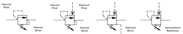
From these symbols, we can see that pressure at the inlet (internal pilot) area A1 and at the external pilot area A2 can force the valve open and pressure at the spring chamber area AD will oppose the force on the opposite side of the poppet to hold the valve closed. The spring chamber can be drained to the exhaust port of the valve (internal drain), drained separately to tank (external drain), or referenced to atmosphere (seal poppet to spring chamber and spring chamber in air).
Next, we need to understand the force balance on the counterbalance spool to determine the pressure required to open the valve and start to move the load (called the release pressure). In order to hold the load, the valve cracking pressure setting must be set higher than the load pressure. Because of the hysteresis (friction) of the valve moving parts, there is a difference between cracking and reseat pressure (the pressure at which the valve closes) with the reseat pressure being lower than the cracking pressure. For this reason, the setting on the valve for the typical counterbalance valve setting is roughly 30% above the load pressure to insure the reseat pressure will be high enough to hold the load.
The images below show the working areas of the counterbalance poppet and corresponding force balance.
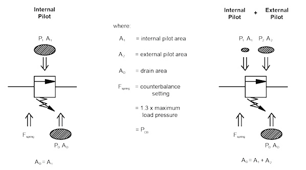
From this, we can derive equations for release pressure based on the actuator type, area ratios, and the load conditions. Keep in mind that from basic statics pressure at the inlet of the actuator can build pressure at the outlet of the actuator across the internal working areas. The following is an example with a single-rod cylinder with rod pointing down and load pulling the rod out:
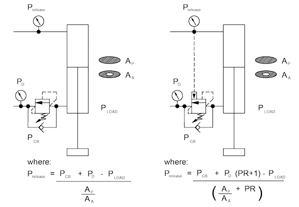
Now consider four load states with a single-rod cylinder, load pulling the rod out so we can understand where an external pilot can be used to decrease the release pressure and increase system efficiency, especially with varying loads:
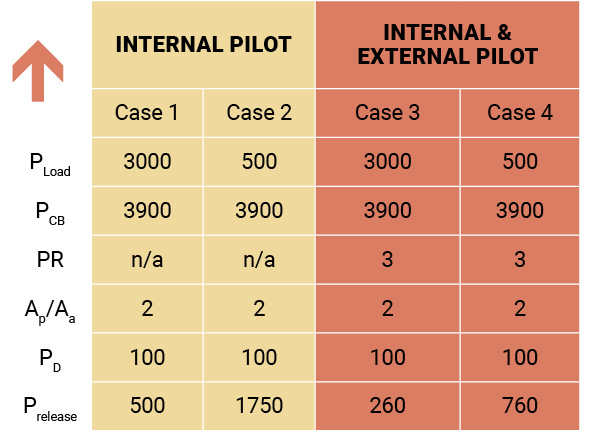
So you can see that for the internally pilot valve, when the load is high, the release pressure is low, but when the load gets light, the release pressure is high. We should always let gravity do most of the work of lowering, if possible, while still being in control of the load, this is the most efficient. We should not be using high power to lower a load. So if the load is constant, then an internally piloted counterbalance valve is the correct choice, as it will always be set the same amount above the load.
For the externally and internally piloted valve, you can see that even at maximum load, the release pressure is lower than the internally piloted valve because the pressure pushing the load down is acting on the internal and external areas at the same time, and the total area is four times just the internal area. Again, we should not be building to high pressure to lower a load—efficiency wise is does not make sense—so an internally and externally piloted counterbalance valve will work more efficiently with varying loads.
For each of these cases, pressure at the exhaust of the valve was assumed to be 100 psi. You will see from the force balance above that for an internally piloted valve that any pressure at the exhaust of the valve is directly additive to the spring setting of the valves, meaning its cracking pressure is increased by that amount. For the internally and externally piloted valve, pressure at the exhaust of the valve will add to the spring setting by a factor of four for a 3:1 pilot ratio valve. For this reason, the designer must determine the pressure at the exhaust of the counterbalance to make the decision whether to use an external spring chamber drain to lower Prelease.
So to summarize:
- The counterbalance valve setting should be 30% higher than the load, so select a valve spring range that allows for this setting.
- Internal pilot, direct acting valves are typically used for constant loads. They can be used with varying loads, but system efficiency will suffer.
- Internally and externally pilot direct acting valves are used varying loads. This will improve the system efficiency.
- An external spring chamber drain must be used when there is excessive pressure build up at the exhaust of the valve to lower the release pressure, (i.e., a meter out flow control or proportional dcv).
We have covered one part of the puzzle regarding counterbalance valves. The next part will review the dynamic operation of the valve once it has opened and the load starts to move.
Share this information.
Related Posts

Offshore Technology Conference Attendance Remains Strong in 2015
Filtering Compressed Air to Protect Equipment & Processes
Displacement Cylinders vs. Regeneration Circuits
Turning Cylinder Failure into Real Value: 10 Key Factors In Selecting A Repair Facility
Case Study: Building an Industrial Hydraulic System
The Role Of Robotics And Cylinders In The Fluid Power Industry
Sponsor

Sponsors