Simulating a Piezoelectric-Actuated Hydraulic Pump Design
Hydraulic pumps are often the focus of automotive engineers attempting to reduce energy losses. For example, power steering systems have progressed from purely hydraulic to electro-hydraulic and even purely electric to make the system more efficient. Working together, engineers at Fraunhofer LBF and Ricardo Deutschland GmbH developed a pump design that leverages piezoelectric actuators, offering both a significant reduction in energy losses and improved response time. Simulation enabled them to verify that the design met specifications. It also reduced development time by 50%.
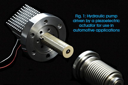
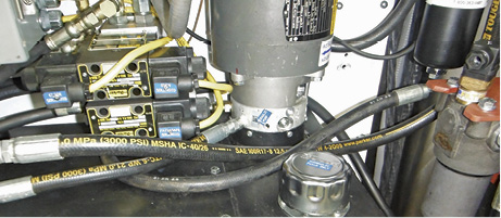
In automotive applications, piezo-actuated hydraulic pumps have mainly been used in applications that require low flow rates and pressures (Fig. 1). For automotive control systems, pressures of 20-200 bar are necessary, which is much higher than the pressure produced by pump designs currently in series production.
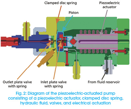
To create a design that produces the pressures required for automotive control systems, it was critical to simulate the entire system, including the pump, valves, and actuator (Fig. 2). We could not rely solely on separate simulations performed in domain-specific tools, because improving the efficiency of a system that unites multiple physical domains requires system-level optimization. The ability to calibrate and validate the models was also critical, because the models we use range from extremely detailed finite element models to system level. The high-level system models help us keep run times as short as possible and enable wide-ranging parameter variations. Using Model-Based Design to develop the pump enabled us to increase the output pressure of existing designs by a factor of 10.
Selecting the Application and Pump Architecture
For our new design, we chose the pump used in selective catalytic reduction (SCR). SCR systems are used in diesel engines, where strict emission and fuel economy requirements are motivating the development of efficient emission controls. The pump injects a liquid reductant into the automobile exhaust stream, which promotes the conversion of nitrous oxide into diatomic nitrogen (N2) and water. The reductant in our system is Adblue®, a urea solution. Our pump must produce an output pressure of 50 bar to deliver a high-quality spray that will improve the mixture.
Using SimHydraulics®, we were able to test different pump architectures to find the one most likely to enable a piezoelectric actuator to develop the pressure required while maintaining its fast response. To minimize costs, we wanted an architecture that uses only one pump rather than designs requiring the additional feed pump to achieve the required pressure. Tests in SimHydraulics let us refine the pump specification by determining the input pressure and spring stiffness for the input and output valve springs.
During architecture selection, we tested the sensitivity of the design to various component parameters. We determined that the ability of the pump to meet specifications was heavily influenced by the design of the clamped disc spring, which forms the seal for the pump chamber. The simulations from SimHydraulics were helpful in determining the spring design requirements (minimum and maximum spring rate, geometry, and disc stiffness).
Incorporating a Detailed Design into the System-Level Model
Finite element analysis was useful when we designed the clamped disc spring. To find a design that offered the minimum bending volume, maximum delivery chamber volume, and minimum stiffness, we used a tool developed in-house by Ricardo. Design of Experiments methods were used to identify the optimal design. We incorporated the spring behavior into the SimHydraulics model to see if the overall system still met the design requirements with the new clamped disc spring.
The check valves are crucial to the performance of the pump. Engineers working on the project have extensive experience with these types of valves, so they customized the standard SimHydraulics components to obtain exactly the effects they wanted to capture in their model. Simulation analysis showed that the eigenfrequency of the pump valves needed to be very close to the operating frequency of the pump to avoid interactions with the natural frequency of the system.
At the start of the design, the team used ideal actuator models to ensure that the required force stayed within a range that a piezoelectric actuator could produce. Next, we introduced Simulink® models of piezoelectric stack actuators to verify that the dynamic performance of the actuator would still enable the pump to meet system-level requirements. The amplifier and power supply were included in the model to add the electrical portion of the system into the simulation.
Comparing System-Level Performance to the Specification
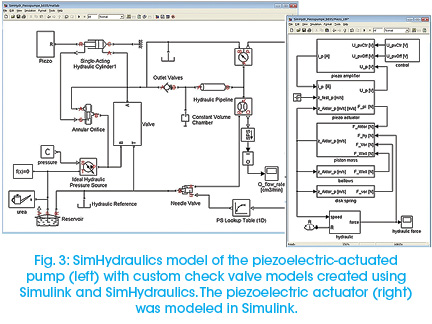
Engineers simulated the entire system within the Simulink environment (Fig. 3). The complexity of the hydraulic system, with multiple valves, fluid compressibility, hysteresis, and multiple flow paths, would have been extremely difficult to model without the blocks that SimHydraulics provides. The team used MATLAB® to post-process simulation results and ensure the design was meeting system requirements.
Simulation showed that we would need to adjust the command signal and amplifier to achieve the desired pressure profiles. The results also showed that the architecture with the optimized design for the clamped disc spring met the pressure requirements for the piezoelectric-actuated pump.
We verified our simulation results on actual hardware. The first prototype that we built verified the simulation results and met the pump specifications. Without the ability to simulate and verify the system’s performance in a single environment, we would have had to rely on separate simulation tools and hardware prototypes. It would have taken twice as long to create the design, and it would not have been possible to increase the output of the pump by a factor of 10, which was required for this design.
For more information: MathWorks is a developer of mathematical computing software for engineers and scientists. Visit www.mathworks.com.
Share this information.
Related Posts


3 thoughts on “Simulating a Piezoelectric-Actuated Hydraulic Pump Design”
Leave a Reply
Sponsor

Sponsors
how did you model the piezo? can you sedn the block that the piezo is made from?
Wow, I didn’t know that piezo-actuated hydraulic pumps can be used for many things. I think I’ll buy some nanopositioners for sale from a good company so that we can improve our existing designs on pumps. This way, we can sell our pumps to the automotive industry and hopefully make a breakthrough in new technology as well.
This wonderful article is addressing topic on piezoelectric actuated pump. I loved reading this article. Here all the information regarding the topic is so easy to understand. Such content must be made more and more available. Thank you for this article! This is really very informative. They offer same information here Primepump.co.nz one must check them also.