Scrap Steel Winder Problem Slowing Down
 Workers at a coil steel-processing mill received rolls of stainless steel from its parent company to slit in half and trim the edges approximately 1″ to 2″. They recoil the sheets and ship them to their OEM customer that fabricates stainless steel refrigerators.
They have a hydraulic motor-driven unit that coils the scrap edges of the coils onto drums. This operation needs to keep up with the speed of the splitter, or the scrap starts to “bunch up,” which requires the workers to stop the line and remove the excess manually. The hydraulic unit was over 20 years old and needed updating. A local hydraulic distributor built them a new unit, and the mill did the installation.
During commissioning, they found that the new unit could not keep up with the slitter line speed as the scrap coil increased in diameter.
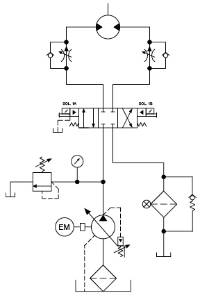
The unit was upgraded from a fixed-volume open-circuit design to a closed-circuit pressure-compensated pump design to improve energy efficiency. The only other difference was the use of a flow-control module under the pilot-operated directional valve. The old unit had line-mounted flow controls.
The builder convinced the mill that it must be the mill’s existing motor leaking more flow to the case, as the pressure increased when the scrap steel diameter increased, causing the motor to slow down. They then replaced the hydraulic motor with a new one, but they still had the same problem.
Any idea what the problem could be?
See the Solution
The reason the hydraulic motor on the slitter slowed down was the use of non-pressure-compensated flow controls in the module mounted under the directional valve. They missed the fact that the original flow controls were pressure compensated. With non-pressure-compensated flow controls, the flow they pass decreases as the pressure drop across them decreases. The pump compensator setting stayed consistent, while the motor pressure increased as the scrap coil diameter increased, reducing the flow. Replacing them with pressure-compensated flow controls solved the problem.
By Robert Sheaf, CFPAI/AJPP, CFPE, CFPS, CFPECS, CFPMT, CFPMIP, CFPMMH, CFPMIH, CFPMM, CFC Industrial Training


Variables missing here….. anyway I have seen these slitter/winder in the field and most are controlled by compensated pumps and proportional valves with feed back for changes in weight to assist with changes in load and speed. Motor needs to be of a correct torque/speed with respect to time it cuts and with a closed centered DVC on a motor circuit which may or may not have free wheel I don’t see any reliefs in the motor legs. Back to the drawing board.
operating psi setting on pump compensator is set too close to the max psi required to wind up the scrap material. as the scrap drum increases, the torque required to wind up the scrap increases which increase the psi requirement. the psi compensated pump will begin to come off stroke a few hundred psi before the compensator setting, decreasing the GPM delivered to the hyd motor. I would also remove the flow controls and allow the motor to rotate as fast as it needs. the scrap winder isn’t going to over power the slitting line, it will pull tension on the scrap and will only rotate as fast as the line allows.
As the roll diameter increases, speed and flow decrease as expected (assuming constant FPM), but the torque requirement increases. could the pressure compensator setpoint be too close to the pressure (torque) requirement of the process near the end of the run, and the pump is beginning to de-stroke?
Most likely the pressure compensated pump’s compensator setting is too low.Once the pump outlet pressure reaches this setting, the pump output flow rate is near aero.
Set the compensator just 150 to 200 psi lower than the relief valve cracking pressure.
Low pressure return filter could be clogged or undersized, causing reduced flow through the drain line from the motor or enough back pressure to compensate the pump.
Once the load increases the pump pressure is satisfied and goes of stroke (compensates) thus reducing the flow to the motor. A pressure compensated arrangement will not work in this condition if the induced motor hydraulic load is at or near the compensator setting. Should have used a load sensing control configuration.
The system needs pressure compensated flow controls.
Well, I can’t believe no one else has weighed in, so here goes, I may nail it spot on or miss it by a mile.
First, I see the flow controls are reversed, set to meter-in instead of meter-out, which causes me to wonder if the motor receives enough flow to spin at the required speed as the size of the coil grows. Secondly I wonder if they are even necessary as the pump is variable volume and max RPM could be set with the pump.
Next, From the start I have wondered about the pump. In a nutshell, it seems that the max. volume should be set higher to achieve the required speed, and the pressure compensator (and relief valve) settings raised so that the pump will drive the motor at the pressure required by the larger coils without cutting back volume. My guess is that the comp pressure is too close to the required working pressure and the pump is compensating instead of driving the load.
Thank you for the opportunity to comment, I look forward to seeing the correct answer soon.
Fred
Hello
Since the motor is working with different loads depending on the scrap load, I think Load Sensing control must be considered on this circuit.