Select Components for Hydraulic Systems: Calculating the Thrust for a Toggle Mechanism
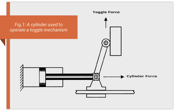
Toggle mechanisms are used where high locking forces are required. Die casting machines, injection molding machines, and coining machines all make use of toggle mechanisms. There are three methods of creating toggle force. They are single lever, double-lever anchored, and double-lever scissors. Fig.1 illustrates a single-lever toggle force mechanism with a moving pivot at the rod end, allowing the cylinder rod to extend and retract in a horizontal plane. Toggle force is exerted upward in a vertical plane as the rod extends. The cap end of the cylinder is often mounted to a pivot.
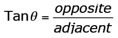
For a single-lever toggle, the upward force of the toggle can be calculated from the tangent of the angle between the lever arms and the horizontal:
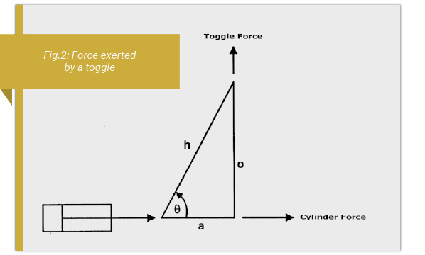
Where “o” (opposite) = the vertical direction and “a” (adjacent) = the horizontal direction. The hypotenuse is equal to the length of the lever arm. Knowing remaining stroke length, the adjacent side (a) and applying the Pythagorean Theorem, the opposite side of the triangle (o) may be calculated:
Hypotenuse2 = adjacent2 + opposite2 Or:
Lever Arm2 = vertical axis2 + horizontal axis2
The Pythagorean Theorem is usually written as c2 = a2 + b2, though it has been rewritten here in an attempt to clarify the concept of the toggle mechanism.
The action of a cylinder rod extending horizontally to exert a toggle force vertically is shown in Fig.2.
The equation representing the force developed by a single arm toggle is:
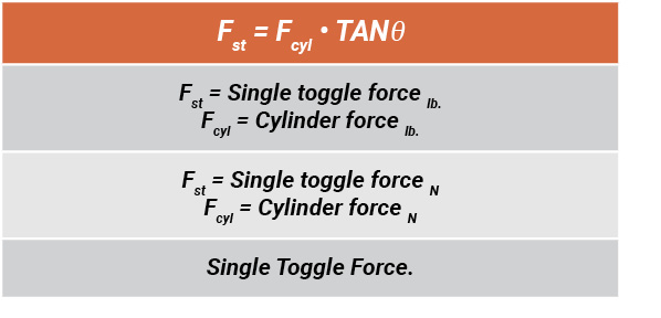
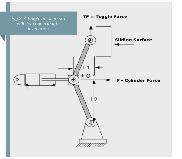
For lever angles less than 45° from the horizontal plane, single arm toggle force is less than the cylinder force in extension; for lever angles greater than 45° from the horizontal plane, toggle force is greater than the cylinder rod force in extension. As the cylinder nears the end of its stroke as it extends, the toggle force is many times the magnitude of the rod force. In Fig.3 the double-lever toggle method with the bottom arm anchored at a pivot point is shown. The cylinder must be free to pivot as the toggle moves. In order to input full thrust into the toggle when the toggle reaches the vertical overcenter position, the cylinder must be mounted so that its axis is perpendicular to the toggle when the toggle is at the overcenter point. If the cylinder is not perpendicular when the toggle is at the overcenter point, it will be acting at an angle to the load and its thrust into the toggle will be reduced. When using a double lever toggle, the system must be kept in balance (Fig.3). A double lever toggle system will require twice the force to lift a load as a single lever system. Thus the following equation can be used:
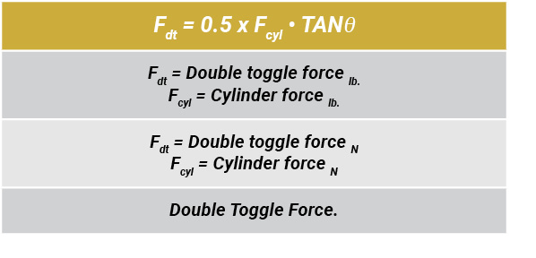
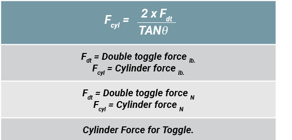
A derivative of this equation is:
TEST YOUR SKILLS
1. If a cylinder rod exerts 23 kN of force extending, how much force would a single lever toggle exert when the 300 mm lever arm (h) is 25 mm (a) from the vertical axis (o)?
a. 36 kN.
b. 200 kN.
c. 275 kN.
d. 276 kN.
e. 280 kN
2. Referring to Fig.3, A cylinder with a 3 in. bore pushes a double arm toggle with arms 12 in. long. The cylinder has a supply pressure of 2,000 psi. When dimension L1 is 8.49 in., what will be the available force from the toggle arms?
a. 7,070 lb.
b. 9,993 lb.
c. 14,140 lb.
d. 19,986 lb.
e. 28,280 lb.
See the Solution
1.c, 2.a
Share this information.
Related Posts


Sponsor

Sponsors