Slip-In Logic Valve Circuits: An Art and a Science
By Jon Rhodes, CFPECS, CFPAI, President, CFC Industrial Training
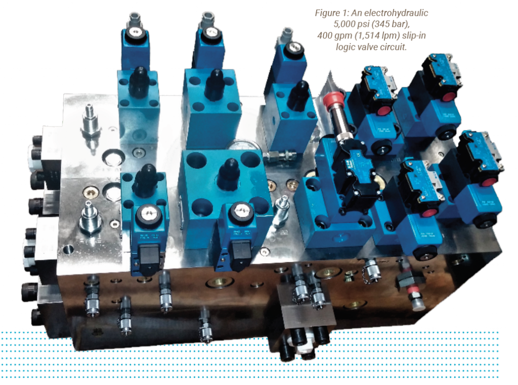
Art and science blend to form the efficient and demanding modern hydraulic circuits used in heavy industries. This is the case with slip-in logic valve circuits, which are used in demanding applications that require long-life, low leakage, and high flow. Hydraulic valve circuits can be packaged in several unique ways depending on the application and working environment in which they exist. The way the valve systems are housed makes the packages look different, even though they are operationally remarkably similar.
As the hydraulics industry has matured, these valves systems now conform to ISO standards for ease of interchange and global implementation. Standard and custom manifold configurations are commonplace to eliminate excessive plumbing and leak points while providing compactness in valve circuits with many flow paths.
Valve packaging and terminology can overcomplicate hydraulic circuits and systems. The tendency in the industry had been to create unique words and subsystem descriptions to allow brand-to-brand differentiation when engineering and analyzing circuits. Modern dogma is breaking these tendencies to demand global standardization. Valve circuits can be packaged in four unique methods, and combinations of these methods are commonplace. Slip-in cartridge, screw-in cartridge, modular industrial interchangeable, and sectionals are the lion’s share of valve-circuit packaging types. Sectional valve stacks were born in the mobile industry out of the demand for compactness.
Of the four types, there has been little standardization in the sectionals, and each manufacturer designs its valve systems with low regard for standardization. Each individual section may have multiple circuit function, making standardization between manufacturers difficult.
Screw-in cartridge technology has become wildly popular. The need for lower cost and compactness drive the industry toward the flexibility this type of system offers. The modular stacking valve systems were born out of the demand for quick replacement and global standardization. These systems used a common valve pattern to communicate flow and are the shining example of standardization in the hydraulics industry. The valve mounting and flow communication interface patterns conform to an interchangeable ISO standard on flow volume and are delivered in D03, D05, D07, D08, and D10 flow sizes.
Sectional, modular, and screw-in technology have their limitations for standard, commercially available component purchase and configuration into working hydraulic circuits when high flow is necessary. These components are typically purpose-built for their flow, pressure, and directional functions. For example, when purchasing a screw-in cartridge valve for a relief function, you simply specify a single component part number and get that relieving function in a screw-in valve format that is ported to communicate the oil properly within the machined body or manifold cavity. This is the point where screw-in and slip-in technology greatly differ. Slip-in technology requires multiple components that comprise the working function and are always pilot operated. Each working function of a slip-in assembly requires a two-way, two-position insert assembly and a piloting cover assembly to be mated together on the manifold to form the pressure, directional, or flow controlling function. The insets are designed and sized in pairs with the controlling cover, but optional specification allows for advanced functions in the matching. The controlling cover hydraulically pilots the insert to open, close, or modulate based on the combination of cover and inserts. The insert and cover must be engineered or analyzed individually and as a pair to ensure proper function.
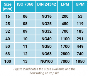 The machined cavities in the manifold accept the inserts and communicate the working A and B pilot or drain ports to the ISO-7368 standard. This ISO standard is derived from the original German DIN 24324 standard. Some will still use the DIN terminology when simply describing the slip-in assembly as a DIN valve. The term logic valve is more commonly used in Europe, as inherent hydraulic logic exists in these circuits resulting from multiple two-way, two-position valves communicating fluid within the manifold to form the overall circuit function. The size of the valves relates to the internal flow capability and range in size from 16 mm to 100 mm, as shown in figure 2.
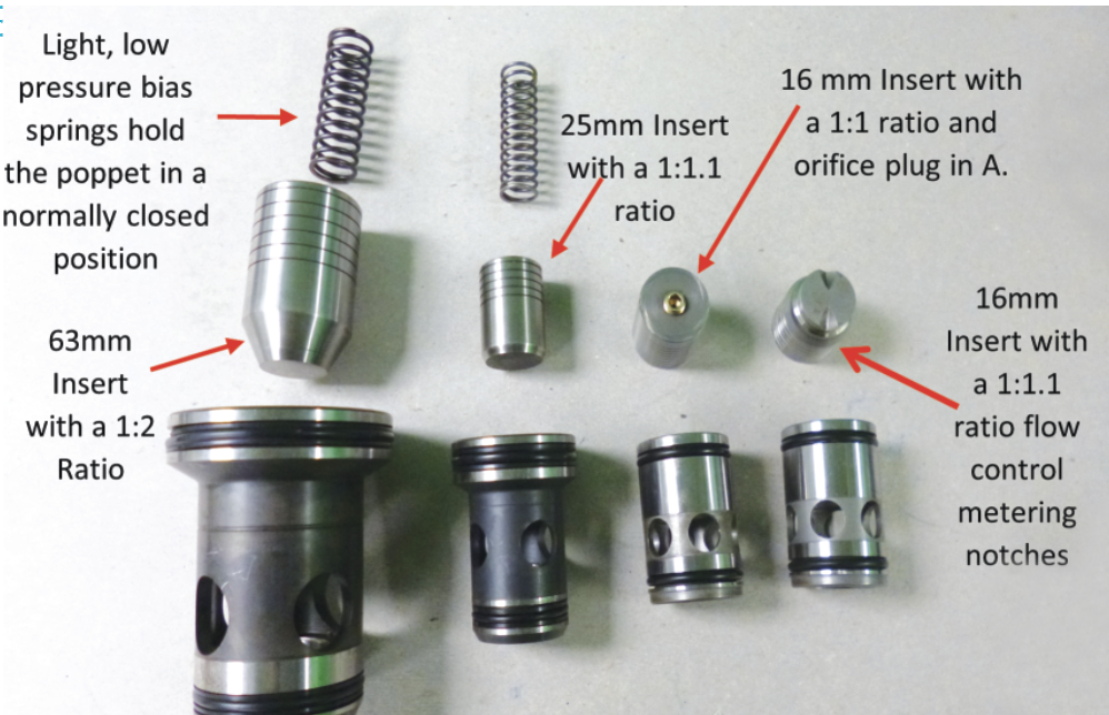
The insert assembly itself has two working ports that control the high flow and high pressure generally used within the circuit to power the actuator. These ports are labelled A and B, with A most commonly being the inlet. The simplistic design of a poppet and sleeve with no soft sealing make this construction the most bulletproof design in the hydraulics industry. The moving poppet either allows flow, blocks flow with minimal leakage, or modulates to meter flow or control pressure. The third port is the pilot port. This port is generally labelled as the AP port. Pressure applied to the AP port acts on the exposed area on the top of the poppet to produce downward or closing force. Pressure applied on the working A or B or A +B produces an upward or opening force. Since force = pressure x area, the poppet opens, closes, or modulates based on the pilot pressure applied at AP versus the pressure applied on A, B, or both.
To complicate this even further, inserts are designed with differential areas on the A port or B port, as compared to the AP port, to bias the poppet to open or closed with different area ratios between the A port and the AP port. This differential area lends itself well to the different pressure, flow, and directional functions. When using the assembly as a pressure relief, it is common to use the 1:1 equal insert so that the pilot pressure at the A port is directly proportional to the piloting pressure within the pressure-relief cover. When using the assembly as a directional function, it is common to use the 1:2 insert to allow pressure at the B port to also open the poppet. When the ratio is not 1:1, the A + B area must equal the AP area.
The cover assembly provides control of the piloting pressure applied to the AP port, and control functions are not dictated by the ISO-7368 standard. Only the dimensions and pilot port locations are covered by the ISO standard. For this reason, the covers can be supplied with a myriad of functions to suit the circuit requirement. The pilot port designations are commonly listed as Ap or Ac, X for pilot pressure, Y for pilot drain, and Z1 and Z2 for auxiliary pressure and drain communication to the manifold. Covers are typically categorized as pressure, flow, and directional function, with options contained within each unique category.
As hydraulic automation continues its march forward, manufacturers produce electrohydraulic proportional pressure and flow slip-in valves and covers that are typically categorized as dynamic. These dynamic assemblies may be supplied with onboard electronics in a single insert-cover combination matched to provide superior pressure and flow function with high accuracy and repeatability. Independent of its function, the cover provides the type of pilot control required for the matched insert. The cover is only controlling the pilot pressure and flow. The main working flow and pressure are ported through the A and B ports on the insert. Pilot pressure supply to the cover assembly generally requires orifice sizing to limit the volume of flow supplied to and drained from the manifold. The size of the orifice and pressure drop across it dictate the pilot flow and drain control to the AP port, therefore controlling the performance characteristics of the assembly. Tuning of the assembly, by changing the orifice size, may be required to optimize circuit performance.
This is the moment when the term art may be used to describe how performance can dictate when, how, and where to place the orifice and to select the correct size. Too much flow will saturate the controlling cover and affect performance. Too little flow will not allow a solid control of pressure to the pilot and cause preopening or chatter. This delicate balance can be mathematically predicted, but rarely do the application loads, forces, and design considerations remain static from design to build, let alone over the life of the working hydraulic machine. If slip-in logic circuits do fail, the failure is most likely due to plugged orifice, as the range of orifice size is between .5 mm (0.019 inches) to 1.4 mm (0.055 inches).
When designing or analyzing these circuits, it is easy to become overwhelmed with the intricate pilot flow paths and inherent applied logic. It is important to break the circuit into the individual working subcircuits and understand each assembly on its own merits prior to considering the entire circuit. The divide-and-conquer method must be used when many functions are contained within a single manifold.
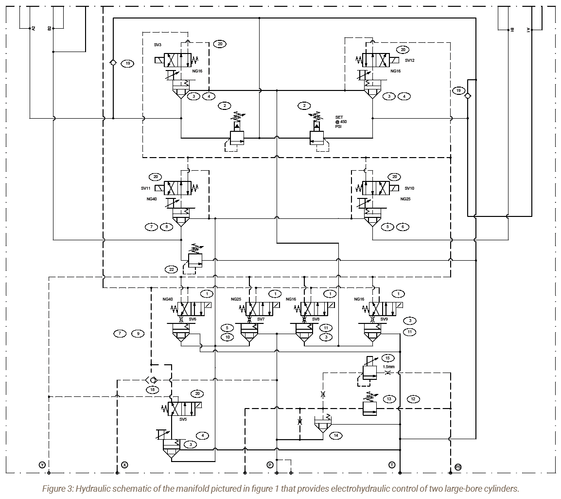
When using solenoid and proportional electrohydraulic control, adding a truth table indicating control signal versus operating function is also crucial to understanding how these circuits works. Adding the ISO colors to the schematics also helps. The schematic shown in figure 3 is designed to control two large-bore hydraulic cylinders from a single pump. Both cylinders can be cycled, but not at the same time. The top section of the circuit selects which of the two cylinders will be operated. The center section controls the directional function for extend, retract, hold, and float. The bottom section controls decompression and provides proportional pressure control for the entire circuit.
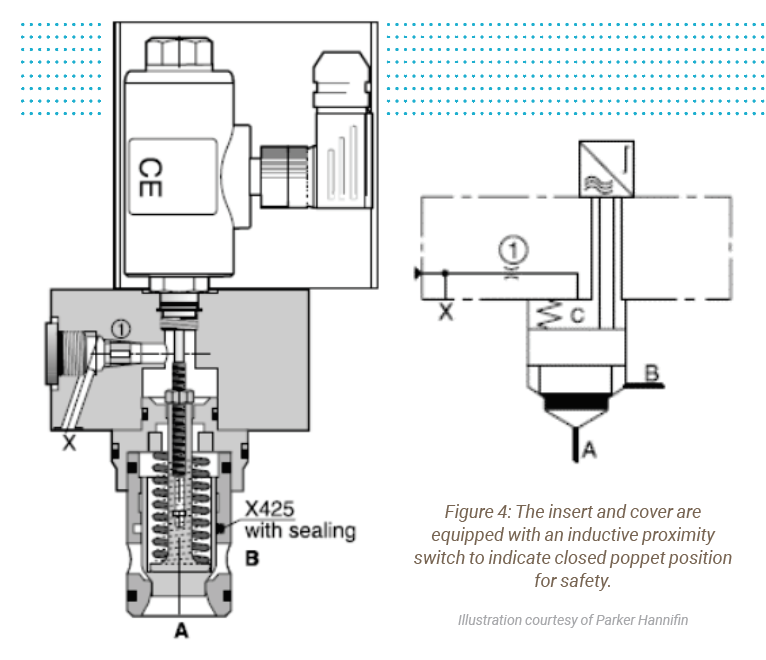
Cartridge valve covers can include electronic position indication of the poppet that is required to conform with machine directives 2006/42/EC (figure 4). Greater hydraulic machine efficiency is realized in the flexibility to match hydraulic horsepower requirements directly to actuator cycling. The reliability of these circuits is unmatched with metal-to-metal-component simplistic insert construction.
Advancements in software design tools make the design and construction of the circuits more palatable than ever. Implementing slip-in cartridge circuits provides superior safety, efficiency, and reliability with the mastering of this art and science.
Share this information.
Related Posts
Compressed Air Systems: Are You Draining Away Your Profits
Choosing the Right Fluid Power Sealing Solutions for Construction Equipment
Improving Wind Turbine Reliability

Energy Efficient Hydraulics and Pneumatics Conference Grows in Second Year

The Value of Fine Fiber Filtration Media

Ergonomic Lifting Made Easier with Vacuum Technology
Sponsor

Sponsors