Test Your Skills: Size a Rotary Actuator
Rotary actuators are used to provide a partial rotation or pivoting action to a component where the space available is not practical for a cylinder and mechanical linkages to achieve the rotational movement. Rotary actuators are used for rotating, mixing, opening and closing, toggle clamping, providing constant tension, bending, oscillating, transferring and flipping, positioning, dumping, and indexing operations. They rotate from a few degrees to several complete revolutions, although most commonly they are less than 360˚ of rotation.
There are five major design types of rotary actuators (figure 1):
- Helical spline.
- Enclosed piston crank.
- Scotch yoke.
- Rack-and-pinion.
- Piston-and-chain.
- Bladder.
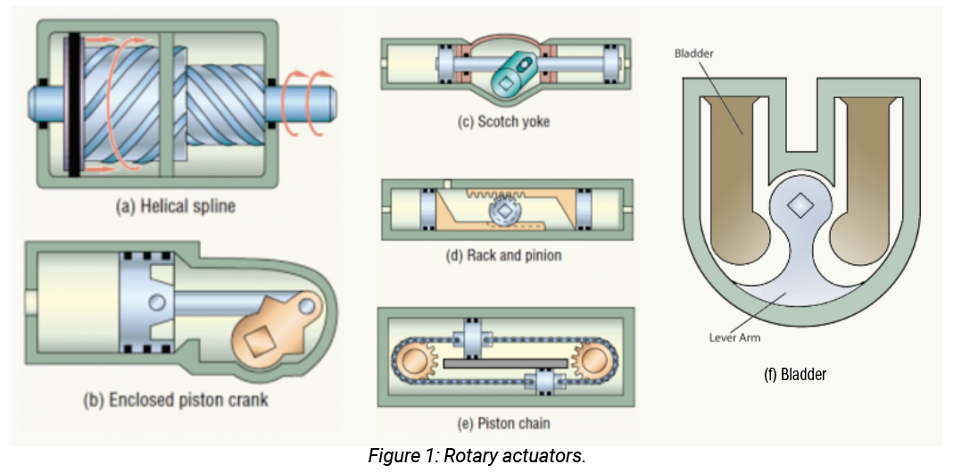
Each of the types have key design features and operational characteristics that would dictate where they are most appropriately applied. For example – the Scotch yoke design provides very high torque at the beginning and end of stroke (approximately double that of the running torque), which is advantageous when the application requires a high amount of breakaway torque to start and accelerate the load. Any mechanical device that employs gearing of some type must take into consideration the effects of backlash during operation and size appropriately.
The efficiencies of the different types are comparable in range, but the amount of output torque and rotational capability differs between them. Because the rack-and-pinion design typically offers the highest torque capability as well as degrees of rotation (50 million lb-in of torque capability and 1,800˚ of rotation), it is one of the most commonly applied. It also provides the benefit of fail-safe holding capability, constant torque in each direction, and ability to withstand heavy side or end loads. It can provide a high degree of accuracy and is therefore used in many precision applications.
A less commonly found rotary actuator is a bladder type. It does offer some inherent advantages due to its design and operational characteristics. It operates on the principle of a pair of bladders in a housing that act against a lever arm to develop torque and rotary motion. Rotary motion is limited (typically to 100˚ or less because of the design) and the amount of torque that can be produced is less than from the other actuator types mentioned. It does offer the advantage of having zero internal leakage and thus is extremely accurate. Additionally, because the medium inside the bladders doesn’t come in contact with the mechanism inside the housing, it is not sensitive to contamination that may be present. The bladder must, however, be compatible with any material that may be used as a lubricant.
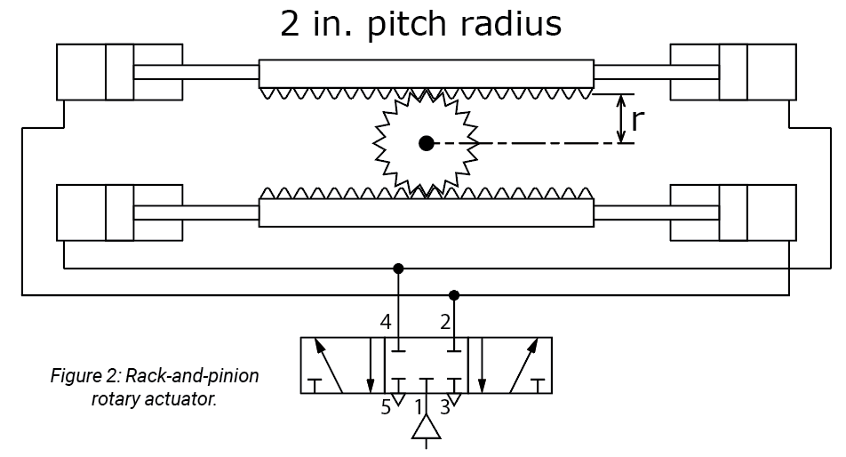
Sizing a rotary actuator is similar in concept to sizing any linear actuator. The first step is determining the torque and amount of rotation required. The torque requirement is in two parts: breakaway or starting torque as well as running torque of the application. Once that is known then a specific type of actuator can be selected. For example – a rack-and-pinion double-acting assembly is shown in figure 2 on the next page.
The torque is a function of two pneumatic cylinders exerting a force on the pinion shaft gear teeth. That force acting over the radius of the gear pitch is the torque generated. Since two cylinders are exerting force at the same time, the effective torque is doubled.
The amount of rotation desired determines what the effective stroke length of the cylinders needs to be. Once that is known, the peak air flow as well as air consumption rate can be calculated as can be done for any cylinder.
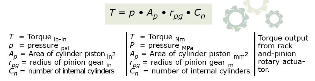
The torque output from the rotary actuator is a function of the pinion gear radius, cylinder bore, and air pressure such that:
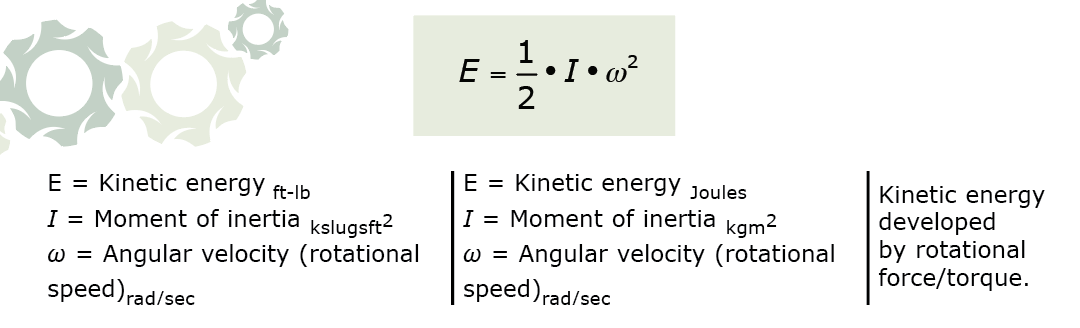
As in pneumatic motors, the more difficult it is to get an object to start to rotate, the more difficult it is to get the object to stop once in motion. This is due to the inertia that exists. The energy that develops (kinetic energy) is a function of the moment of inertia of the object being rotated and the angular velocity (rotational speed). That is too complex a topic to fully describe here, but the kinetic energy must be dissipated safely or damage may occur. Another possible method to minimize the amount of rotational kinetic energy that can be generated and needs to be dissipated is to use an air-over-oil rotary actuator, which can allow for damping. Typically, the kinetic energy would be dissipated using a shock absorber.
The formula for calculating the kinetic energy generated is:
Test Your Skills
What is the total torque produced on the pinion gear shaft of a dual cylinder rotary actuator that has twin bore diameters of 25 mm each and a pitch radius of 50mm? The supply pressure to the rotary actuator is 0.7 MPa.
a. 17.18 Nm.
b. 24.54 Nm.
c. 34.36 Nm.
d. 49.08 Nm.
e. 54.63 Nm.
See the Solution
The correct answer is c.
Share this information.
Related Posts

Sponsor

Sponsors