Test Your Skills: The Application and Operation of Transducers
In closed loop control applications, it is necessary to convert some physical property into an electrical signal to provide a feedback signal to the amplifier. The components that carry out this conversion are known as transducers, and the ones most commonly encountered in electrohydraulic applications are pressure, flow, linear displacement, angular displacement, and angular velocity.
Transducer or transmitter?
Transducers and transmitters are functionally similar instrumentation devices in that they convert one form of input energy into another form of output energy. For example, an input (pressure, temperature, force, or torque) is converted into an electric output signal to be interfaced with a control system. The main difference between the two is the type of electric output signal. A transducer is typically a three-wire device that outputs a signal in volts (V) or millivolts (mV) and is most suited for applications where the distance between the processes being measured and the control system is relatively short (less than 50 feet). In some applications, transducers may be an acceptable choice as they tend to be smaller, are generally less expensive, and have fewer (and in some case no) electronic parts that can fail. However, transducer output signals can be vulnerable to electromagnetic interference, degradation due to voltage losses in cable runs over 50 feet, and provide no immediate indication of a broken wire, or a unit or power failure based on a zero-volt output.
A transmitter is essentially a transducer with additional signal conditioning electronics to convert and amplify a signal. Transmitters are typically two-wire devices with 4-20 mA being the most common output signal. Where signal accuracy or degradation are of concern, transmitters are a much more suitable choice when sending the electrical output signal over long distances or where electromagnetic interference may be present. With a 4-20 mA range, the control system sees 4 mA as the transmitter zero output. Should a broken wire or other malfunction occur, the controls can immediately detect this as an error or failure and react accordingly.
A word of caution on the terms transducer and transmitter. When these terms were first derived, they had distinctly different meanings and operating characteristics. Over time, however, these terms are commonly and many times erroneously interchanged, and several manufacturers do not really distinguish between the two types. And there are some manufacturers that offer both transducers and transmitters with both voltage and current output signals. Anyone specifying, testing, or troubleshooting such devices should be aware of the possible differences and how they can impact system behavior. In this article, unless otherwise stated, we’ll use the more generic term transducer.
Pressure transducers
Pressure transducers normally use a piezo-electric crystal, which has the property of producing an electric charge when a force or pressure is applied to it. The crystals can be stacked in layers to increase the output, which is then amplified to produce a usable electronic signal.
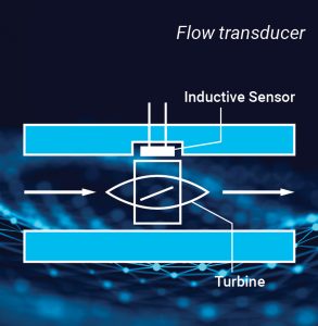 Flow transducers
The most common type of flow transducer is the turbine type, shown in the illustration to the left.
As flow passes through the device, the turbine wheel spins at a speed proportional to the flow rate. Each time a blade passes the inductive sensor, a voltage pulse is produced. The pulsed voltage signal can then be converted into an analog signal proportional to flow rate.
Linear displacement transducers
There are many different devices available to measure linear movement. Factors such as accuracy and environment will normally determine which one is used.
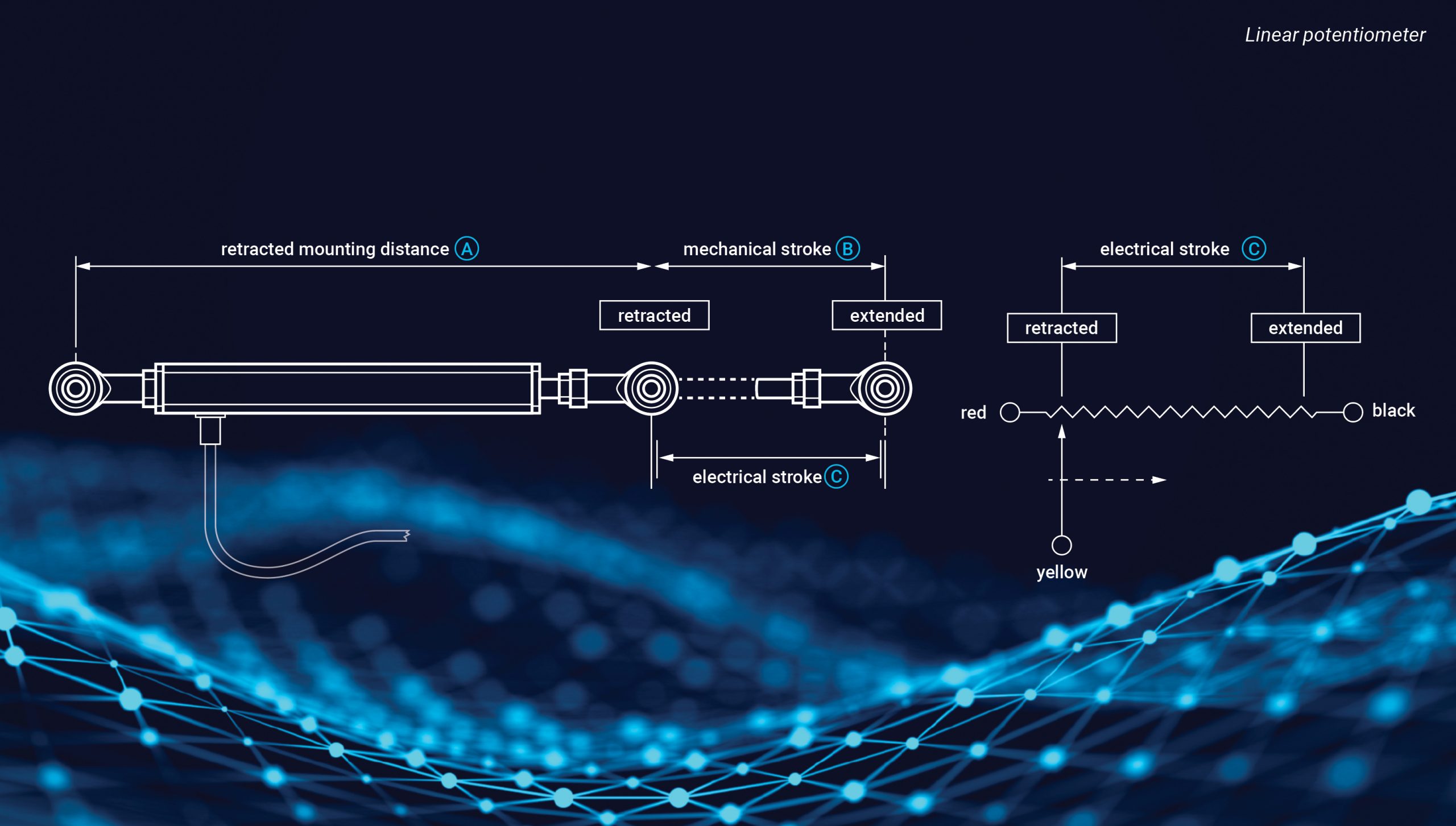
Linear potentiometers
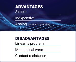
Linear potentiometers are resistive, analog devices used to provide a voltage output signal in proportion to their mechanical displacement and are suitable for simple applications with limited speed and distance requirements. Although inexpensive and simple in design, linear potentiometers can experience linearity deviation due to ambient temperature variations. They typically require signal conversion to interface with modern digital control systems. Potentiometers are most affected by vibration and shock.
Share this information.
Related Posts


Sponsor

Sponsors