Test Your Skills: Understand the Application of Regenerative Circuits
Regeneration is a general term that describes what happens when exhausting hydraulic fluid from the rod side of an actuator is directed back into the pressure line. The exhausting fluid is reused or regenerated to do work. Interjecting the exhausting fluid into the pressure line adds a resistive load to an actuator so that the increase in available flow results in decreased available force. When used on cylinders, it is the rod-end exhaust flow that is regenerated back into the blind-end flow. This creates equal pressure on both sides of the piston. Because of the differential area between the blind end and the rod end, the equal pressure produces a greater force on the blind side, causing the cylinder to try and extend. The force caused by the pressure on the annulus area (the area around the rod) acts against some of the force on the piston. Only the pressure acting on the area of the rod is effective in producing force. This actually makes calculating the characteristics of a regenerative circuit quite easy. It is as though the flow and pressure were acting only on the rod of the cylinder.
While it is common to design regenerative circuits using cylinders with a 2:1 area ratio between the blind end and rod end, any single-rod cylinder can be used for regeneration as long as the force requirements do not exceed what is available from the pressure on the rod area.
Examples of regenerative circuits
![]() Figure 1 shows a full-time regenerative circuit that extends and retracts a cylinder. Full-time means that the circuit is always in the regenerative mode of operation. A circuit of this type would extend and retract the cylinder rod of a 2:1 area ratio with the same velocity and force in each direction.
Figure 1 shows a full-time regenerative circuit that extends and retracts a cylinder. Full-time means that the circuit is always in the regenerative mode of operation. A circuit of this type would extend and retract the cylinder rod of a 2:1 area ratio with the same velocity and force in each direction.
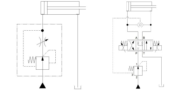
The circuit in figure 2 achieves a fast, low-force extension with full-force clamping by using a bleed-off orifice at the rod end of the cylinder. On extension, the cylinder regenerates at low force until the rod contacts the work piece. When rod extension stops momentarily, the bleed-off valve allows a small amount of flow to return to reservoir, allowing the pressure at the rod end of the cylinder to fall. This allows full pressure to act against the cap side of the cylinder piston, thus developing full force.
As shown in figure 3, another means to increase the extension force of a cylinder under regeneration is to install a counterbalance valve in the line between the rod end of the cylinder and one of the actuator ports of the directional control valve, and a pilot-to-close check valve between the two cylinder ports. This allows free flow from the rod-end port to the cap-end port. Shifting the directional control valve to extend the cylinder directs fluid to the cap end of the piston. Return flow from the rod end of the cylinder regenerates through the check valve to join with pump flow as the counterbalance valve prevents fluid from the rod end of the cylinder from returning to tank through the directional control valve. When the load pressure rises above the pressure setting of the counterbalance valve, the pressure rise is sensed through the external pilot line connected to the cap end of the cylinder. The counterbalance valve then opens, venting the rod end of the cylinder. As the load pressure rises, the check valve seats, allowing pressure to continue to rise in the cap end of the cylinder. Thus, full-force extending is developed after the load pressure rises. When the directional valve is actuated to retract the cylinder, the pilot-operated-to-close check valve is piloted closed, preventing the flow of fluid from the rod end to the cap end of the cylinder. This allows retraction of the cylinder.
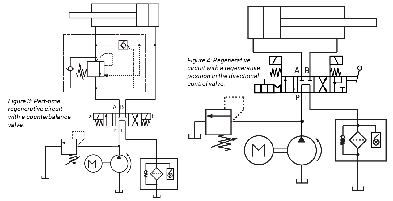
Figure 4 illustrates a circuit that allows selection of a regeneration option with a fourth position in a four-way directional control valve. The fourth position connects both ends of the cylinder with the pump while blocking flow to tank. For a 2:1 cylinder, this gives the options of fast extension at half-maximum cylinder force and slow extension with maximum cylinder rod force. The regenerative position in the directional control valve looks similar to a float position except that both cylinder ports are connected to the pressure port rather than to the tank port.
A point to note regarding the 4/4 directional control valve in figure 4 concerns the placement of the centering springs and solenoids in the symbol. ISO 1219-1 allows for envelope lines to be extended and for alternate locations of operators in an attempt to clarify the operation of the valve. The centering springs are shown to center the valve to a certain center position, with the fourth position controlled by the operation of the lever.
Test Your Skills
The regenerative circuit in figure 2 has a 63-mm bore and a 45-mm diameter cylinder rod. If maximum cylinder pressure is set at 110 bar, what force will the cylinder rod exert after the cylinder stalls?
a. 17,494 N.
b. 22,275 N.
c. 34,290 N.
d. 174,940 N.
e. 342,898 N.
See the Solution
The correct answer is c.
Share this information.
Related Posts


One thought on “Test Your Skills: Understand the Application of Regenerative Circuits”
Leave a Reply
Sponsor

Sponsors
can you please send me the complete solution