The Effects of Pressure Compensated Components on Control Systems
Pressure Compensation (Hydrostat Function) with Proportional Directional Valves
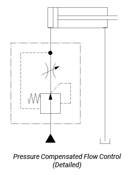
To maintain a relatively constant flow to an actuator regardless of variations in inlet or load pressures, a pressure compensated flow control can be used to achieve and maintain a somewhat regulated speed. This type of control typically consists of a normally open pressure control (essentially a pressure reducing valve) in series with a fixed or manually variable orifice (flow control). In this application, the normally open pressure control is commonly known as a hydrostat and can be located either upstream or downstream of the flow control. A 100-150 psi bias spring (typically) holds the hydrostat in the normally open position. See the figure below. With the hydrostat sensing the pressure both upstream and downstream of the flow control and therefore both supply and load pressure, a constant pressure differential equal to the value of the bias spring can be maintained, regardless of changes in the sensed pressures. By maintaining a constant pressure differential, a regulated flow relative to the setting of the flow control valve can be obtained. Assuming that a proportional directional valve is essentially an electrically adjusted flow control, it can be seen that a hydrostat can regulate flow is a similar manner.
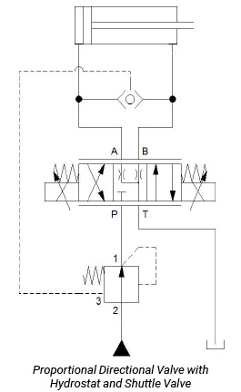
 In the example shown, a hydrostat is connected to the P port of a 4 port, three position proportional directional valve. The valve A and B work ports are connected to the inlet ports of a shuttle valve and the shuttle output is connected back to the hydrostat. In operation, when the proportional valve is shifted, pressure at the outlet of the hydrostat (port 1) is picked up by the pilot line and is ported back to hold the hydrostat in the open position. At the same time, load induced pressure developing at the active work port (in this example, port A) is sensed through the shuttle valve and is ported back to the hydrostat (port 3). This load induced pressure along with the bias spring acts to hold the hydrostat in the open position. The outlet pressure acting to close the hydrostat and the load induced pressure trying to keep it open cancel each other out. It is the bias spring then that keeps the hydrostat in the open position and is, therefore, what determines the differential pressure across the proportional valve inlet to the active work port. It is this differential pressure that limits the flow rate across the proportional valve for a given displacement of the valve spool. This technique is called restrictive, meter in pressure compensation. Other types of pressure compensation include 3 port bypass using a normally closed pressure control and post pressure compensation which is used primarily in mobile valves and is not part of the scope of this article.
Although hydrostats used for pressure compensation to regulate flow can provide for a relatively constant actuator speed, their application does not come without an impact on performance, potential cost and physical size. Since a hydrostat only allows for a pressure differential equal to the bias spring to be realized across the proportional valve, flow for a particular proportional valve size will be limited versus being non-compensated. This means that a larger valve than otherwise required may be necessary to pass the specified flow. Larger valves have bigger spools with more mass and require more solenoid force to shift against heavier centering springs. They require more time to move and are not as quick to respond to an input signal as a smaller valve flowing at a higher pressure differential. Should the flow rates be high enough to dictate the need for a pilot operated, two stage valve, the pilot valve itself will contribute to the overall response time of the proportional valve. Smaller valves respond faster and are more sensitive to changes in input signals thereby controlling output flow.
 When rapid response and high accuracy are of concern (as typically is the case in industrial systems), one must exercise caution in using pressure compensation for flow regulation in systems that utilize closed loop feedback control. This is particularly the case in the fast acceleration of high mass loads to a target position or velocity. It is also true if the mechanical system has an inherently low natural frequency where the hydrostat is yet another spring-mass system that can introduce disturbances as the feedback loop modulates the proportional valve to target the system set point.
Another area of concern is with tractive (overrunning) cylinder loads that are controlled with a proportional valve having a symmetrical (equal flow area) spool. If the cylinder has a large diameter rod relative to the piston diameter, the resulting high differential area requires the proportional valve to be significantly restricted to maintain control of the load. This tends to cause cavitation in the piston end of the cylinder and may require a different type of proportional valve spool or additional circuitry to prevent potential stability issues. See the text “Know How to Size the Proportional Valve” earlier in this section.
When properly applied, pressure compensating hydrostats can be a practical means regulating flow but are most effective in open loop (non-feedback) systems.
Test Your Skills
Pressure compensating flow controls are most effective where?
a. In high response and high accuracy systems
b. Open loop systems
c. Overrunning loads
d. High flow rate systems
e. Systems with low natural frequency
See the Solution
The correct answer is b.
Share this information.
Related Posts

Test Your Skills: Stopping & Holding Loads Safely

Adding Hydraulic Fluid to the Reservoir

Sizing an Air Motor
Test Your Skills: Calculate the Oil Flow Rate & Pressure From a Pneumatic Intensifier
Test Your Skills: Hydrostatic Transmissions

Test Your Skills: Hydraulic Components in Circuits–Mobile Valves
One thought on “The Effects of Pressure Compensated Components on Control Systems”
Leave a Reply
Sponsor

Sponsors
I am curious as to who created the content of this article.