Turn It Off!
If it’s not needed, then don’t use it, right? An obvious statement, but so rarely is this philosophy employed when using compressed air-powered venturi systems. This article explains the benefits of using a single venturi with compressed air control valves instead of multiple venturi units in a vacuum pick-and-place application that employs numerous vacuum cups.
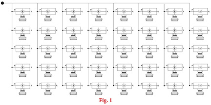
Fig. 1 shows a very typical multiple-cup vacuum lift system. Each vacuum cup is connected directly to its own dedicated single-stage venturi. This system, although effective in its fundamental task, uses considerable compressed air to operate. Assume that the cup diameter is 50 mm (2″) and the lifting rig is handling non-porous plastic sheets. A suitable venturi for this application would use about 1 cfm of compressed air. There are a total of 40 vacuum cups and associated venturi employed. Therefore, the system would have a total air consumption of about 40 cfm. This equates to about 10 hp or 7.5 kW of compressed energy to operate. I’m sure you’ll agree this is significant.
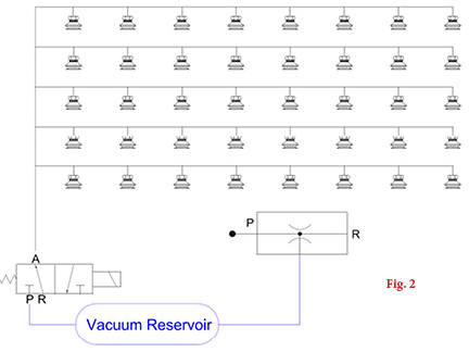
Fig. 2 shows the same vacuum cup array but utilizes a single larger compressed air-driven venturi or vacuum generator. However, this venturi is a multistage unit, which offers a better operating efficiency in regards to compressed air vs. vacuum air intake. A suitable venturi for this system uses about 4 cfm of compressed air. That’s certainly a lot less than in Fig. 1 and equates to an energy consumption of about 1 hp or 0.75 kW.
However, the venturi in Fig. 2 would not have the same vacuum flow as all of the single units employed in Fig. 1. Therefore, a vacuum “reservoir” is utilized between the vacuum venturi and vacuum cups. Also installed is a suitable vacuum control valve. Vacuum “energy” is stored between the venturi inlet and the vacuum valve, indicated by the blue lines on the schematic. This also removes the concern of some users where single-stage units are used due to the faster cycle time to reach a safe vacuum level. The “ramp-up” speed of a multistage unit is often slower than a single-stage model. By utilizing the reservoir and vacuum control valve system, this “ramp-up” time is virtually eliminated. As soon as the vacuum valve is opened, vacuum is applied to the cups virtually instantaneously.
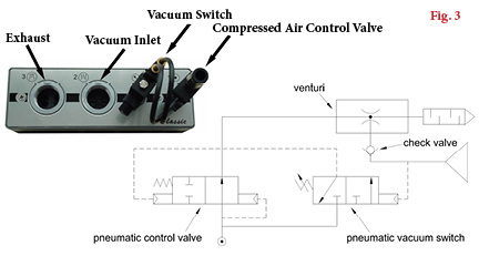
The venturi also utilizes an energy-saving circuit comprised of the circuitry as shown in Fig. 3. When the reservoir volume reaches a preset point of 24″Hg (80% vacuum), for example, the venturi will automatically shut off. During this period, compressed air is not being used. When vacuum is required at the cups, the vacuum valve will open and the energy stored in the reservoir will offer vacuum force to the cup. If the reservoir is large enough, the decrease in the vacuum level within the circuit could be within the hysteresis of the vacuum switch on the energy-saving circuit. If this is the case, the venturi will remain off.
Only when the vacuum level within the circuit falls below the hysteresis point will the vacuum venturi restart and recharge the circuit. Therefore, unlike the venturi used in Fig. 1, the single multistage venturi will ONLY be on when it is required to recharge the circuit.
Applications using the circuit shown in Fig. 2 can use as much as 90% less compressed air if the ancillary components are selected and installed correctly.
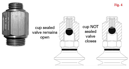
A disadvantage of this circuit, as is commonly discussed during presentation to the vacuum user, is that if one of the vacuum cups fails to seal, the complete circuit could fail. This is true. Accessories, such as self-closing valves shown in Fig. 4, could be installed at each vacuum cup. Once the cup is placed against the load to be lifted, if the valve “senses” air flow because the cup is not correctly sealed or is damaged or the load varies in size each time, the valve will CLOSE, isolating that particular cup from the rest of the vacuum circuit, which will maintain a full system vacuum.
Alternatively, if the load being handled changes in size in only one direction, such as different lengths of steel sheet, then individual control on “zones” could be implemented by installing extra vacuum control valves.
By utilizing the latest vacuum technology and consulting with vacuum application engineers rather than just the salesperson, different methods of vacuum generation can be reviewed, and the best, most efficient system can be employed based on the application. This article offers a simple yet rarely used method of multiple vacuum cup handling with minimal compressed air consumption. As with most applications, there are many methods of achieving success. With some thought and dialogue with the vacuum user, a near-perfect solution is never far away.
This article is intended as a general guide and as with any industrial application involving machinery choice, independent professional advice should be sought to ensure correct selection and installation.
Share this information.
Related Posts


Sponsor

Sponsors