Vacuum Pick and Place: High-Speed Cycle Time Reduction
By Dane Spivak, and illustrations by Daniel Pascoe, Davasol Inc.
In the world of high-speed factory automation, speed is everything. Manufacturing processes require fast cycle rates to increase output and overall production efficiency.
This article discusses strategies to implement in vacuum pick and place applications to minimize production cycle times. There are many contributing factors with some more effective than others. However, as we all know, every fraction of a second counts.
Vacuum Cup Selection
The most important part of vacuum cup selection is determining a model that offers an adequate seal to safely lift the product. If this is achieved, the following cup characteristics are to be considered in cycle time reduction – cup style, material, and internal volume.
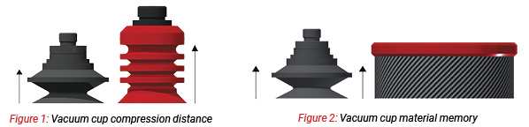
The style of a cup will determine how long it takes for the product being gripped to meet with the datum point inside of the cup. Or in other words, the time it takes for the cup to compress under vacuum.
Figure 1 compares a flat-ribbed cup to a multiple bellows cup. As indicated by the arrows, the distance the cups must compress before meeting its datum point (the internal base of the cup) is drastically different. The lesser this distance, the less time it takes for the cup to compress.
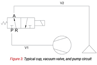
The reverse effect of compression can also disturb cycle rates. Commonly referred to as material memory, the cup deforms under vacuum, and when vacuum is released and the product is dropped, there is a time consideration while the cup returns to its original state of rest.
Figure 2 shows two cups with the same compression distance. The foam cup on the right has poor material memory compared to the rubber cup on the left. This means the foam cup needs more time to return to its original state to start the cycle.
The internal volume of a vacuum cup determines how much air needs to be evacuated to achieve the desired vacuum level. Since the lip diameter of the cup is directly related to the lifting force, the first step is to size the diameter of the cup correctly to lift the parts securely.
Ideally the smallest diameter of cup should be chosen to reduce the inner cup volume. Next, we look at the inside of the vacuum cup and how much volume of air it contains. Again, ideally, we would like to reduce this volume as much as possible. Reverting back to Figure 1, the flat cup on the left is preferred to the bellows cup on the right.
Conveniently enough this aligns with the compression aspect of the vacuum cup previously discussed.
So what can we conclude from the aforementioned? When selecting a vacuum cup for a high-speed application, it is best to use a small, flat, low-volume cup with good memory.
Vacuum Valve Location
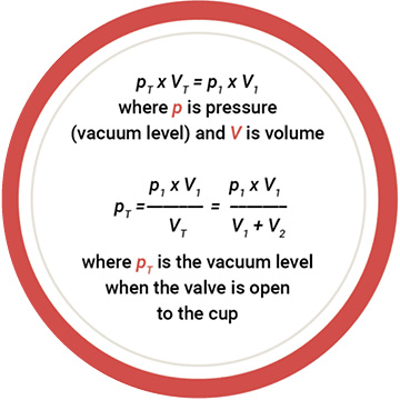
In a typical vacuum pick and place application, the vacuum valve is located somewhere between the cup and pump to turn vacuum on or off as demonstrated in Figure 3. The valve location is critical to the pick and drop speed of the product.
Assuming the pump is running constantly, the vacuum line between the pump and the valve acts as a vacuum reservoir and “recharges” the vacuum line when the valve is closed. This volume, which we will refer to as V1, is important as we will see in the following analysis. When the valve opens to allow vacuum to be applied to the cup, the air from the valve to the cup lip is the volume of air to be evacuated. This is the other important volume, which we will re refer to as V2. The sum of volumes V1 and V2 will be referred to as VT.
To decrease cycle rates, the goal is to have a high ratio of V1/V2. A larger volume of V1 will allow for a more efficient vacuum reservoir to evacuate V2. A smaller volume of V2 results in less air to be evacuated with the assistance of V1. Not only that, the V2 volume is related to the drop speed as well. The smaller the volume in V2 means less air to reintroduce and consequently less time to release the part. To further increase the release (exhaust) speed, a pulse of compressed air can be applied during the exhaust cycle.
Back to the V1/V2 ratio, let’s apply the ideal gas law to this concept and see how it affects the vacuum level.
Let’s consider two scenarios with different volumes while the pressure is constant. We won’t use units for simplicity. Arbitrary numbers have been chosen below.
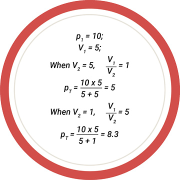
As shown in the above calculations, we see that when the V1/V2 ratio increases the initial vacuum level of the system is higher when the valve opens. This means that the overall vacuum level is higher and the pump needs to remove less air to achieve its highest desired vacuum level. The result is a quicker reaction of the cup and reduced time to meet faster cycle rates.
Another quick note about vac-uum valves. The cycle speed of the valve itself and flow capabilities will provide different results. Quicker cycled valves and flows which match the pump performance are critical. Flow will be discussed in further detail in the coming sections.
Choosing Your Pump
It’s well known that vacuum generation units are key to the performance in any system, and it is no different in high-speed applications. Popular pick and place pumps include vane pumps, regenerative blowers, and air powered venturi generators. There are many more options but, in all cases, related to cycle time, the area of focus is vacuum flow.
Vacuum flow, typically measured in cubic feet per minute (CFM) in North America, is the volumetric rate at which air is removed from a system. Flow is different from vacuum level. Vacuum level is the result of removing air from a system, which creates a pressure lower than atmospheric. Usually relatively high vacuum levels are easy to achieve, but getting to that vacuum level as quickly as possible is dependent on the flow. Higher flow pumps will achieve the final vacuum level sooner and decrease the cycle time.
All vacuum pumps have published flow ratings though these listed numbers can be interpreted differently. Specific types of pumps will result in different flow performances, even if they have the same listed value in literature. Let’s continue using the CFM units previously defined. Most flow ratings listed in data sheets or catalogs are associated with the pumps SCFM rating. This is the standard cubic feet per minute measurement, which is correlated to the pumps flow performance at standard temperature and pressure. In our case, this is an ambient temperature of 68°F (20°C) at an atmospheric pressure of 14.7psia (0.1 MPa) when the pump initially starts to run. However, the ACFM ratings, actual cubic feet per minute, is often more important to the overall performance of the pump. The ACFM ratings are flowrates at different vacuum levels (lower atmospheric pressure).
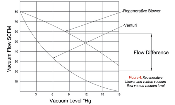
Figure 4 compares a regenerative blower curve to that of a venturi. Both units have Both units have comparable SCFM ratings of 80SCFM though the curves demonstrate that ACFM values create a substantial gap. If we consider the values at 12”Hg, we can see that the blower offers around 50ACFM, while the venture only provides 10ACFM. The blower is pulling an additional 40CFM. We conclude that the blower provides shorter evacuation times to reach vacuum levels between zero and 18”Hg. What we learned from this analysis is that the listed ratings of pumps provide limited information. The flow vs vacuum level curve should be understood to truly maximize cycle speed.
Although they may not be the ideal type of vacuum generator for high-speed applications, venturis are often implemented in pick and place. Venturis consume compressed air to generate vacuum and are used for their low cost, low weight, and application simplicity.
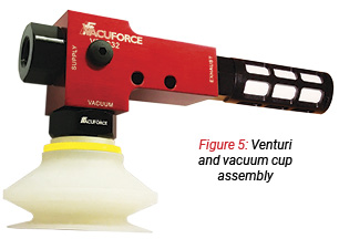
As shown in Figure 5, a vacuum cup is often close-coupled to the venturi for point-of-use generation. Single-stage venturis offer quicker pick speeds than multi-staged units. This occurs because multi-staged units have multiple stages that the compressed air must travel through as the name suggests. Single-staged units have one stage, and therefore, react faster.
Venturi reaction speed also relies on the pneumatic plumbing arrangement. A smaller volume of compressed air that must travel to reach the venturi will take less time to initiate vacuum generation. As with the vacuum valve, the pressure valve should be mounted as close as practical to the venturi.
Vacuum Cylinders
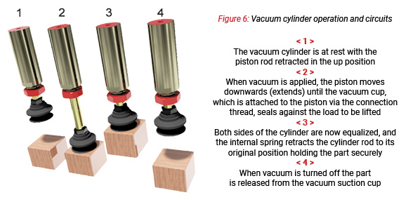
The vacuum cylinder is a product that is generally not well known though it can offer many benefits, particularly in high-speed applications. Vacuum cylinders are used to provide vertical positional movement of vacuum cups often referred to as the z-axis travel. They can often replace pneumatic and electric cylinders and use the existing vacuum source from the cup to power the cylinder. Figure 6 breaks down the function of the vacuum cylinder step by step.
Vacuum cylinders are quick reacting. The cylinder has a maximum stroke, but if the cup seals against the product anywhere through the piston stroke, it will instantly retract, resulting in cylinder cycle times of fractions of a second.
Sizing Parts
We’ve touched on vacuum flow and CFM ratings in this article and its importance to pick up speed. This concept is applied throughout the vacuum system with every component from the pump vacuum port right down to the vacuum cup. All other interconnecting components, fittings, and hose should be sized accordingly to the pumps performance.
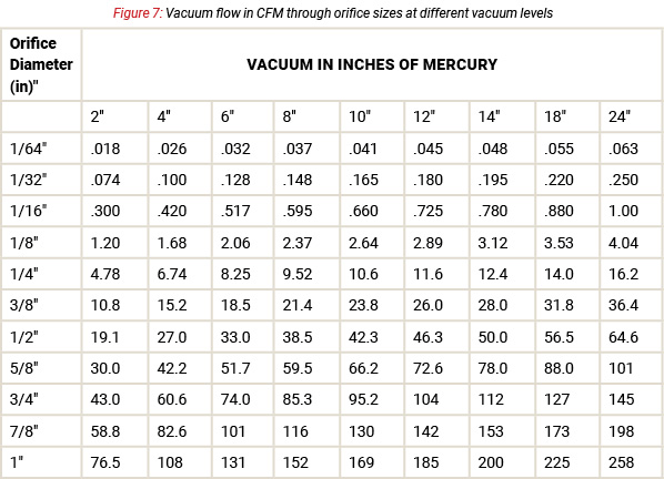
Figure 7 shows a table of vacuum flow through orifices of different sizes. Each component of the vacuum system should be sized so the appropriate amount of flow can be handled. If one portion of the system restricts the flow, it affects everything downstream from that point. One weak link can cause significant effects. Tubing or hoses should be chosen so that their flow rating is equal to or greater than the flow rating of the pump. Note that when vacuum lines or components are in parallel, the flow capacity can be added together.
Other factors potentially decreasing flow performance are having unnecessary long lines or sharp turns in fittings and hose. Straight through flowing parts and smooth flowing vacuum lines are always a benefit. Lengthy hose can result in frictional flow losses and vacuum level drops.
Conclusion
In this article, we’ve covered a few strategies to reduce cycle times in vacuum pick and place applications including cup selection, vacuum valve location, pump choice, vacuum cylinders, and sizing components. These strategies are a technical guide to assist in understanding fundamental principles. Each application is unique and should be studied independently to find which solution is the best fit.
Share this information.
Related Posts


Sponsor

Sponsors