Validating Aircraft Hydraulics with a Full-Scale Test Cell

In many competitive application areas, engineers and designers are faced with steadily increasing pressures to keep pace with innovation and new technology, get to market faster, and optimize resources, both in cost and in man-hours. This is especially true for today’s commercial and military aircraft industry, where there is little room for error, and components must not only work individually, but must also integrate seamlessly with a complex system with numerous variables and external influences.
Hydraulic systems in today’s aircraft present substantial challenges for designers. For example, designs must be lightweight, high performance, reliable, and cost effective. After designing the system with specific component types and sizes—such as valves, pumps, motors, and tubing—and detailing their locations and inter-component routing paths, designers must then verify the performance of each component, as well as performance for the overall system. They must ensure proper function under a long list of normal, adverse, and even extreme conditions, including temperature swings, thermal cycling, and g-force. Each component must function per the design intent, and the entire system must work together as anticipated.
Given the complexity of aerospace systems and their mission-critical nature, designers must verify the system dynamics, transient response, and load capacity on the ground prior to deploying it into an aircraft. Similarly, component vendors want to ensure—with a high level of confidence—that the final set of selected components and arrangements are compliant with system-level specifications before shipping the components to the end user.
This testing process is complicated by the number of factors that can affect overall system performance in addition to the performance of individual components. Component arrangement, configuration of interconnect tubing, and even the system routing can all add variables that must be considered, tested, and addressed. Obvious problems, such as improperly sized and selected components (valves, pumps, or reservoirs), for example, will negatively impact performance. But less-obvious problems, such as tube size and even bend radius of tubing, can cause significant and sometimes unexpected performance issues. All these variables must be considered individually and as part of the whole system.
Since component suppliers must find and resolve system-level problems to optimize performance and accuracy, it is imperative to conduct a credible, in-depth assessment of the complete configuration’s performance in the most efficient and reliable way possible.
Case Study
An aerospace hydraulics component vendor contracted Wineman Technology Inc. to build a test stand using actual components, tubing, and configuration to create an exhaustive test suite for performing data analysis.
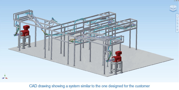
To begin the project, the customer provided 3D CAD geometry files of the aircraft hydraulics design, along with a detailed bill of material (BOM) for the hydraulic components to be used, many of which were specifically designed for this aircraft and required component-level testing prior to system-level testing (Fig. 1).
The geometry files were converted into a form that could be used by a numerically controlled bending machine to produce tubing to match the exact aircraft geometry and volume. The accuracy of the tubing bends was critical for proper system-level testing because it allowed designers to validate the design and routing of the tubing while simulating actual flight maneuvers using the hydraulic components in the aircraft.
Steel tubing was used for this testing since the actual magnesium tubing is expensive, hard to obtain, and difficult to modify for sensors and fittings. This carefully constructed system matched volumetric conditions to better than 1%, including tubing bends, lengths, and diameters. As a result, it was a very close replication of the actual aircraft’s set-up, and could be used to test and assess operation with high credibility and low risk.
Instrumentation and Software
To instrument the test stand, National Instruments CompactDAQ hardware was used, a rugged data acquisition platform that integrates connectivity and signal conditioning into modular I/O to directly interface with sensors and signals.
NI CompactDAQ includes
- Sensor-based I/O modules with signal-conditioning functions (amplification, filtering, excitation, and isolation) for accurate sensor measurements
- General-purpose I/O modules supporting a broad range of analog and digital input and output
- Chassis and controllers to control the timing, synchronization, and data transfer between I/O modules
In addition, by using NI LabVIEW software, Wineman created a custom user interface, allowing the customer to build test profiles, run durability cycles (such as ramping a pump through speed cycles), and operate control valves to simulate user flaps with the actuators (prime movers) under load. Thanks to its 50 kSPS data acquisition rate, the system could provide accurate measurement of transient impulse respond—a critical concern where “shock waves” (similar to water hammer) and their detrimental effects are a major concern.
Results
The final turnkey solution delivered allowed flexibility and customization, with options for adding additional test requirements later as desired. Using LabVIEW, the customer could schedule repeated “hands-off” tests with loops or specify a number of simulations, such as 20 bank turns or 45 take-off/landing cycles, adding varying operating conditions if desired.
A hardware-based test stand such as this one addresses the multiple challenges that today’s product suppliers, designers, and OEMs face including
- More complex designs
- Increased performance demands
- Additional constraints of size, cost, and power
- Shorter project completion times and tighter deadlines
- More comprehensive testing required before delivery
- Less time for redesign
- Increased reliance by end-users on component suppliers to provide configurations and detailed BOMS to meet specs with a high level of confidence and low risk
- Necessary adherence to detailed regulatory standards for performance verification
Why Modeling and Simulation Alone Will Not Work
There’s no doubt that today’s modeling and simulation tools are advanced and powerful, and have improved by several orders of magnitude in just a few decades. Today’s finite element analysis (FEA), computational fluid dynamics (CFD), and hydraulic applications can deliver impressive results in many situations and within reasonable time. As a result, a software-based model and simulation approach may seem a technically attractive approach for an aircraft hydraulics-related test and verification project in terms of cost and time, but it doesn’t capture the reality of the design and implementation.
A real-world hydraulics system has many hard-to-model aspects, including variables that are seemingly mundane yet are quite important, such as the effect of bends in tubing (gently curved, sharp 90° turn, or with a radius somewhere in-between) on fluid flow and pressure. Even if the model is approximately accurate—it could be, if enough time and effort is put into it—the problem is that a real system has hundreds of these tubing bends. All modest individual approximations and their associated errors in the model add up to a large aggregate error in the subsequent simulation. This makes the model’s result nearly useless except as a very rough “first-pass” approximation and performance check to see if the design is anywhere close to being adequate. That coarse level of accuracy is, of course, not acceptable given the critical nature of the application and the need to have a high level of confidence in the result.
So, while there may be non-hardware-based simulation alternatives for some situations, designers find that for sophisticated hydraulic systems with complex configurations and critical applications, a hardware-based test rig and appropriate data acquisition/control instrumentation—combined with a flexible user interface—is a very time- and cost-effective solution. It offers minimum risk while yielding a high level of confidence in the result.
For more information on Wineman Technology’s aerospace solutions, or for a free system evaluation, visit www.winemantech.com.
Share this information.
Related Posts

Compressor Room Ventilation
Asset Utilization: The Key to a More Efficient Operation

Revisions to ISO 11171: A Calibration of Automatic Particle Counters for Hydraulic Fluid Power Liquids
Locking Protection is Key to Hydraulic System Safety
Choosing a Closed Loop Axial Piston Pump
Mobile Equipment Reservoir Baffle Innovation
Sponsor

Sponsors