Valve Positioners Offer Improved Control Valve Performance
 Valve positioners have changed the way actuated control valves respond within a process control loop. By adding either a pneumatic or electro-pneumatic positioner to the valve, both single-acting and double-acting actuators can be precisely positioned and controlled. The valve can become an integral part of a digitally controlled system that relays both valve health and diagnostic information to assure that the loop maintains set point within a desired accuracy. This article details the many advantages of installing and applying a positioner to a basic, pneumatically actuated control valve package.
The operation of a control valve involves positioning its plug relative to the stationary seat within the valve. An actuator is directly coupled to the valve plug via the stem and moves the valve plug to the desired control position. A pneumatic or electric actuator is normally used to control this valve plug position. Pneumatically actuated control valves function either air-to-open or air-to-close. Air-to-open valves are normally held closed by a spring and require an air pressure to open; air-to-close valves are normally held open by a spring and require air pressure to close them. The mechanical design of the valve and actuator combination determines which way the actuator functions, but the desired fail-safe condition determines which type is applied (in case of plant instrument air failure).
A computer, controller, PLC, thermostat, or other electrical-controlling device sends an analog electrical signal directly to an electric actuator or through a current/voltage-to-pneumatic converter or electro-pneumatic positioner to a pneumatic actuator. The signal is based upon the desired system set point and modulates the valve linearly more open or more closed. By automating valves in this manner, they can be used to directly and/or indirectly control temperatures, pressures, and flows within an open or closed-loop system.
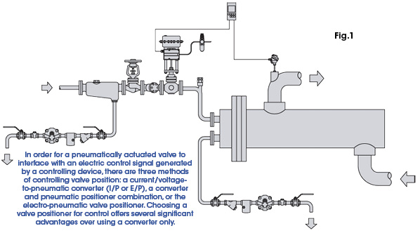
Heat exchangers are a common type of closed-loop control application where both pneumatically and electrically actuated control valves can be used to regulate water, steam, and condensate. A partial graphical representation of a typical heat exchanger utilizing a control valve is shown in Fig. 1.
As modern heat exchange system design demands higher efficiencies, so has the need for improving control valve performance. Closely matching heat exchanger performance with process system demands while generating minimal waste adds up to real savings. The accurate modulation and control of valves that offer fast response and accuracies within 2% of set point adds up to less waste steam and condensate fall-out and removal. Some of the advantages of using valve positioners include the following features:
Faster Speed of Response
A heat exchanger that does not respond quickly enough to temperature changes brought on by process load changes/upsets to the steam system can be caused by something as simple as an incorrect hot water or steam valve or valve actuator being used. Everything from poor system or piping redesign to added demand caused by facility expansion can result in this slow response. Changing from an electrically actuated valve to a pneumatically actuated valve that utilizes a positioner can sometimes make the difference provided the heat exchanger can still meet the facility’s capacity requirements. With the correctly sized pneumatic actuator, the valve reacts faster than its electrically actuated counterpart and can keep up with faster-changing hot water demand.
Control Higher or Varying Differential Pressures Across Valve
If higher differential pressures or varying differential pressures across the valve plug cause the valve position to change, the positioner automatically adjusts the air pressure to the actuator to “re-position” the plug according to the control signal. When a positioner is used, the valve has its own closed-loop control based upon the input signal and stem position feedback. This is accomplished through the stem position feedback linkage, pneumatic amplification relay, and adjustment of the output pressure to the actuator according to the input control signal. This closed-loop control circuit is integral to the positioner and therefore maintains consistent closing and opening forces (thrust) dictated by the differential and valve position.
Control of Large Diaphragm/Piston Actuators
Larger diaphragm or piston-actuated control valves can require increased air volumes, increased forward and reverse flows, and increased air pressures that are not generated by traditional converters (I/P or E/P). For example, a larger pneumatic diaphragm-style actuator may have an internal volume of 0.30 ft3 (cubic feet) that must be filled in order to move a valve fully to the open or closed position. If a positioner is used that has a forward and reverse flow rating of 0.07 scfs (standard cubic feet per second), that same valve will open or close within 4.3 seconds. Without the use of a positioner, the open or closing time can be very long. Most I/P and E/P converters are only rated for 0.02 scfs forward flow volumes and have reverse flow volumes of even less. So a valve may open within the required system response time but close at an unacceptable rate.
Positioners also supply air pressures to the actuator at or near their supply pressures to move the valve into the desired position. They become the “powering force” regardless of how much air pressure (psi) is required to the actuator in order to move the valve where it needs to be to achieve force-balance equilibrium. An I/P or E/P converter cannot and does not operate in this manner. The converter supplies an output pressure based upon the linear electrical control input signal only. Usually, their pressure spans are within 30 psi with normal operating ranges of 3-15, 3-27, or 6-30. Those air delivery pressures can only be changed by 2-3 psi. While the electro-pneumatic positioner may receive the same type of linear electrical control input signal, it is not bound by the calibrated operating range restrictions. It will deliver pressures all the way up to its regulated supply setting to the actuator.
Being able to deliver these higher pressures is very helpful, especially in overcoming the negative effects of hysteresis and deadband that are always present within larger actuator and valve combinations. Friction is the most common contributor to these negative effects and is always in opposition to the air pressure generated from the control signal at dynamic conditions. The positioner is always comparing desired set point with the stem position and adjusting the air pressure to the actuator so that the friction effects are minimized.
Control Action Change
The concept of control action is more easily understood by considering a pneumatically actuated control valve that is air-to-open with an electro-pneumatic positioner installed. With direct control action, as the electrical input signal to the positioner increases, so does the pneumatic output from the positioner to the actuator. The valve opens and modulates proportionally while flow through the valve increases or decreases accordingly.
With reverse control action, as the electrical input signal to the positioner increases, the pneumatic output from the positioner to the actuator decreases. Sometimes system design changes due to piping re-routing or logic control changes within the controller, computer, or DDC require a control valve to operate in this manner. While the use of a positioner cannot change the valve’s function, it can switch its control action from direct to reverse and vice versa.
Split-Ranging Capability
Many domestic hot water heat exchangers have two control valves of different sizes installed on the same control loop to handle wide-ranging system flow demand changes. A split-range set-up of those valves is a common method of calibration and set-up where positioners make this possible. Their flexible span and zero adjustments allow a valve’s travel and stroke to be shifted around within its range. In normal operation, a control valve’s full stroke will follow the full span of the input control signal. For example, an electro-pneumatic positioner that accepts a 4 mA to 20 mA analog input current will normally stroke a control valve from 0% to 100% of its travel respectively. If the positioner is split-ranged, the valve will travel 0% to 100% with only a corresponding 4 mA to 12 mA input current. In both examples, the valve’s span is shifted in relation to the input current signal.
Split-ranging the positioner as described above allows one (smaller) valve to control at lower system demand while the other (larger) valve controls when system demand is higher.
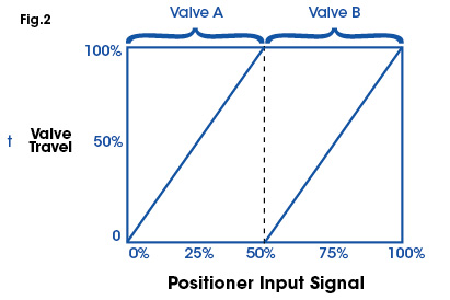
Fig. 2 shows the relationship between the positioner input signal and valve travel when two control valve positioners are split-ranged. Notice that the second valve does not begin to open until the input signal to the positioner is at 50% of span.
Change of Control Valve Flow Characteristic
Installed inherent flow characteristics (design characteristic) of a control valve are determined by the type of plug, seat, cage, etc. that are used. Sometimes that linearization of a non-linear flow characteristic is necessary so that the process valve gain is constant, regardless of the controller output. Changing or adjusting the flow profile is necessary to tighten control accuracy and improve performance. Depending on the design and type of positioner, linearization can be accomplished by switching a mechanical cam or by digitally/electronically reprogramming a new performance curve into the positioner. Utilizing a positioner to change the inherent flow characteristic can be a more cost-effective solution than installing a new valve or changing out the valve trim.
Limited Travel with Reduced Lift
Reducing the amount of lift or limiting a valve’s travel is sometimes required in a control system for performance or safety reasons. Valves are sometimes mistakenly oversized, resulting in inefficient operation at the lower 5-10% of their travel. Similar to split-ranging the input signal to match the full stroke of the valve, as described in the previous section, the positioner’s pneumatic output signal can be compressed to match the full electrical signal input. This allows full input resolution of the control signal to be applied to the first 5-10% of the valve stroke. But there is a trade-off between a valve’s ability to respond to small control signal changes and having more input span resolution. Hysteresis and deadband effects are greatly amplified and can negatively affect control valve performance with such a high “turndown.” Operating a control valve in this manner should only be a temporary measure until an appropriately sized valve can be installed.
Sometimes a valve’s travel or lift is limited for safety reasons or process protection. If the positioner’s set-up and calibration is changed for these reasons, the installation of a mechanical travel stop should immediately follow. Mechanically limiting the travel assures that the valve will not open beyond this point in the event of a positioner failure and does not cause an unsafe condition.
Digital Communications/Diagnostics Capability
Microprocessor-based electro-pneumatic valve positioner designs have not only allowed manufacturers to move away from using mechanical cams for determining stroke (and flow) characteristics, but they have also offered the ability to embed significant intelligence and communications into the electronics. This can be very advantageous when interfacing the positioner to control systems that utilize digital communications, such as HART®, BACnet®, Modbus®, or LonWorks® protocols.
Sensors within the positioner now provide information associated with valve stroke and thrust, output pressures to the actuator, enclosure temperature, valve seat/plug wear, and valve performance. On-board diagnostics and alerts are commonplace within digital valve positioners along with historian data logging of abnormal valve performance events. But added intelligence does come with an added cost.
Depending on the type of digital positioner selected, the added technological complexity can be intimidating. In order to take advantage of the additional information, sometimes operations, engineering, and maintenance personnel must become familiar with many more control parameters and process variables. Software utility applications that allow valve positioner interfacing to a central computerized control system or PC are the most common methods of monitoring and changing those parameters. Using a software utility can ease the complexity through its display of graphical views of valve parameters. The software helps the end user interactively set-up, tune, and maintain the control valve/positioner and save the configuration into a software file for later reference or download.
The use of a valve positioner can solve simple and complex control valve problems along with offering significant performance and accuracy improvements to a control system.
About the Author: David Matherly is a product manager for controls and instrumentation with Spirax Sarco, Inc. He has more than 30 years of experience in instrumentation and controls, and has held engineering, product management, marketing, and technical positions. For more information, email david.matherly@us.spiraxsarco.com or visit www.spiraxsarco.com.
Share this information.
Related Posts


Sponsor

Sponsors