ASG’s S2A LVDT Signal Conditioner Geared to Nuclear Power Plants
 By Alliance Sensors Group
Nuclear power plants use large hydraulically operated valves to control steam flow to the power turbine. These valves require rugged and reliable electromechanical position sensors, usually LVDTs or LVRTs (inductive half-bridges), to give valve position feedback to the turbine’s computer control system. These inductive position sensors use specialized electronics known as signal conditioners for operation and to produce the required signals for the control system.
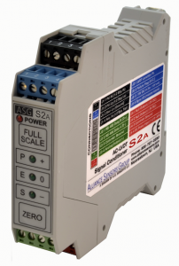
Expressly for the power-generation industry, Alliance Sensors Group offers its model S2A LVDT signal conditioner module with distinct features significant to power utilities, including cybersecurity protection, system diagnostics, high module reliability, and real-time system recalibration capability.
Cybersecurity protection
ASG’s S2A smart modules are microprocessor-based electronic products, so most power plant users, especially nuclear power utilities, and users in related industrial process facilities are naturally concerned about potential vulnerabilities to cyberattacks. For this reason, S2A modules incorporate significant cybersecurity features to minimize the likelihood of a successful cyberattack.
Foremost of these protections is the lack of a physical or electronic connection to the internet. While an RS-485 half-duplex communications port is built into S2A modules for diagnostic and setup purposes, the port has no access whatsoever to the operating firmware of the module. The module cannot be compromised by attempts to access its operating system by any internet-based cyberattack.
However, the RS-485 comm port does permit certain set-up and operational parameters to be adjusted by ASCII commands transmitted over the module’s RS-485 bus. To prevent anyone from tampering with module parameters that had been set up when the module was initially installed, S2A modules offer a lockout feature that not only prohibits tampering with the module’s setup but also notifies the control room and security personnel in real time of any attempt to tamper with the S2A module.
This lockout feature can be initiated over the RS-485 bus with an appropriate user command or can be physically set at the module itself by using a specific locking process. In either case, the module cannot be unlocked over the RS-485 bus. It can only be unlocked and reset by an authorized person who has been instructed in the unlocking process, which must be applied to the module itself. That person must have been cleared by facility security and be physically present inside the facility at the S2A module site.
When an S2A module is locked, it will respond to informational data commands from the control room or a DCS, but it will react to transformational commands or actions such as setup change as tampering. If an attempt is made to tamper with a locked module, either on-site at the module or via the RS-485 bus, the module’s front panel LEDS will flash continuously, the module’s failure warning switch will trigger an alarm, and a tamper code will be output onto the RS-485 bus for delivery to the control room personnel.
System diagnostics
The S2A offers fault or failure detection for high-reliability applications like nuclear power plant turbine controls. The S2A’s diagnostics can detect at least eleven fault conditions of the sensors and module, including shorted, open, or disconnected primary; shorted, disconnected, or open secondaries; analog output shorts or current loop opens; and the most common hook-up errors that can occur during initial system installation and setup. Detected errors or faults can set off alarms and drive the analog output out of range, which is particularly important for applications using redundant LVDTs, especially nuclear power plants. With the S2A in its operational mode, the front-panel LEDs indicate specific failures by the various LEDs being steady on, flashing on and off, and alternating between blinking and steady on.
In addition to the local visual indication by the LEDs of a failure or fault, the S2A also provides electrical outputs that allow the failure warning to be transmitted to a remote indicator, the system controller, or an alarm device. These outputs include a failure signal using an open collector switch, driving the analog output to an out-of-range value, and numerical error codes displayed over the RS-485 bus. The S2A manual contains a full table of the detectable failures, their LED status, and their diagnostic error codes.
Any operational failures will activate the failure-warning output signal from an open-collector transistor switch to operate a relay, alarm, or a pull-up resistor for a TTL output pulse. This switch’s factory default is NC (normally closed) but can be changed to NO (normally open) by an RS-485 command. The failure warning switch signal has a short, programmable delay (default setting: 200 msec.) before its activation to eliminate trips from noise spikes, a nearby lightning strike, or any similar kind of electrical transient.
Besides this continuous output failure-warning switch signal, the S2A module offers another electrical failure notification by driving the analog output to an out-of-range value of voltage or current. Unlike the open collector switch failure output, this out-of-range output signal has no built-in delay time. Typically the DCS (digital controllers) used with redundant sensor systems sample the sensors’ outputs at a fairly high rate and have built-in software algorithms to reject any sensor’s output that is outside the expected range of values. By not allowing an in-range output from a faulty sensor to be an input to the controller, the failure of a valve position sensor is prevented from disrupting or tripping the turbine’s control system.
Module reliability
The S2A LVDT signal conditioner module has a large number of electronic components, but it exhibits excellent reliability because the components are operated substantially lower than their maximum electrical and environmental ratings, typically at 50% or less. As a result, the S2A has a conservative MTBF that is based on a reliability analysis according to MIL-HDBK-217F for the pc board assembly used in the S2A by itself, which is then used to analyze the complete S2A module assembly as follows:
S2A PCB assembly: MTBF of 207,640 hours, which covers all pc board components but does not include either the front panel switches and LEDs or the plug-in screw clamp terminal blocks.
S2A module assembly: MTBF of 198,820 hours, which is based on front panel switches being actuated no more than 100 times each, and the plug-in screw clamp terminal blocks being removed and reinserted no more than 100 times each over the lifetime of the module.
Based on these MTBF hours, Alliance Sensors Group rates the nominal MTBF of S2A modules as 176,000 hours or 20 years of continuous operation.
An important reliability factor about S2A signal conditioner modules is that each one undergoes a minimum of 50 hours burn-in using rapidly cycling on-off powering to discover any “infant mortality” type of component failures. A reliability enhancement often overlooked is the unvented module case, which prevents the ingress of insects and contaminants that could lead to an S2A module’s failure over time.
In addition to the intrinsic reliability indicated by the MTBF, the S2A incorporates another related feature for system reliability called auto-mastering master/slave syncing. Quite often, when multiple LVDTs and their interconnecting wiring operate in close proximity, beat frequencies can develop if there are slight differences in the excitation frequencies of the modules. If a beat frequency occurs, it produces very low frequency amplitude modulation of the modules’ DC output. The way to avoid such an interaction is to synchronize each module’s excitation to exactly the same frequency so that no beating can happen.
Auto-mastering chooses one module as a master based on the modules’ digital addresses. Up to 15 other modules can be connected synchronously as slaves to the master over the auto-master sync bus. Whether all of the modules are powered up at the same time or not, the module with the lowest digital address at initial power up will become the master. If the master oscillator were to fail, auto-mastering automatically selects a new master to regenerate the excitation signal, providing true fail/safe operation.
Real-time system recalibration
Another unique feature of an S2A LVDT signal conditioner module is the ability to perform a real-time system recalibration. In certain circumstances, it may be desirable to perform a “hot” recalibration on a module. This need typically arises from the effects of thermal expansion and/or contraction on a power turbine’s mechanical system when the initial calibration was done at room temperature, but the turbine valves and their LVDTs are now operating at elevated temperature, and the original calibration process cannot be repeated under these new conditions.
Recalibration permits trimming of either end point’s analog output in a system that is already calibrated, provided the actual output values from the module are within ±4% of the desired full-span output. Recalibration can be used to trim either end point’s analog output independent of the other and is done while the module is operational, so it has an immediate effect on the system’s analog output. Actual recalibration is done with RS-485 commands or by a prescribed sequence of pushbutton depressions.
Additional features
Although the four outstanding features considered above are of strong interest to potential S2A users, there are several more features that are popular with systems integrators and power utilities alike.
- Color-coded plug-in screw terminal blocks greatly facilitate prewiring a control-system cabinet.
- With an S2A, an inductive half-bridge or an LVRT calibration is done just like that for an LVDT.
- Quick and easy pushbutton calibration requires little technician time during installation.
- Saving digital calibration data permits hot swapping modules while the system is in operation.
- The module’s differential input front end reduces the effects of ground loops and input noise.
ASG’s model S2A DIN-rail mounting LVDT signal conditioner module is the most popular and feature-laden LVDT signal conditioner being used in the power-generation industry today. It is the first choice of practically all power plant systems integrators in the Western world, along with numerous electric power utilities worldwide, particularly those operating nuclear power facilities.

