Electrification in Mobile Hydraulic Systems
Elements of this image furnished by Adobe Stock | Rodrigo
By Zach Lindsley, Vice President of Sales, Terzo Power Systems, LLC.
Electrification in hydraulic systems has a completely different meaning historically than the way I think about it today. I remember, not that long ago, jumping in a brand-new Caterpillar Grader with a row of hydraulic pilot-operated valves up in front of the operator’s seat and not a bit of electronics to help the operator prepare the correct grade. Then the uproar occurred when the “M” series graders came out with electro-hydraulic proportional valves and a single joystick that replaced the row of 10+ pilot valve operators. This same transition happened countless times around the same period with every type of equipment out there until mechanical and pilot-operated valves were few and far between. The benefits of having control over the hydraulic system electrically outweighed the downside of re-training operators and service technicians who have been running and servicing the same types of equipment for years. This type of electrification was the key to gaining the efficiencies needed to meet Tier 3, 4, and 5 diesel emissions standards. This unlocked the power of GPS for automatic grade control, along with the extreme precision that these massive machines are now capable of. The next generation of electrification shifts away from the valve bank (kind of, we’ll get to that part) and focuses on the prime mover.
What if we couldn’t use diesel engines anymore? What should our system look like, if we wake up tomorrow and diesel engines are no longer allowed to be used in new equipment and we must make the most efficient system possible to maximize battery life? That’s the question I’m going to try to answer. There will be no debates about the reasoning behind the diesel not being available; we’ll just look at the challenge at hand and hopefully explore a few good solutions.
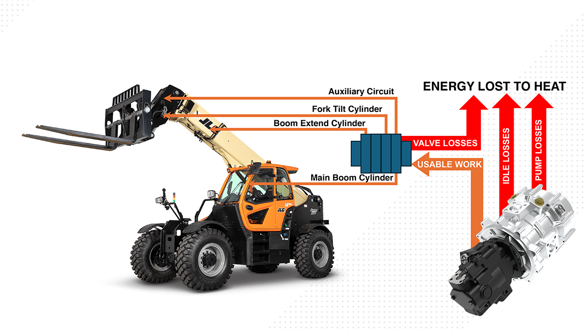
The instinct of most engineers, when tasked with electrifying a piece of equipment, is to simply replace the internal combustion engine with an electric motor. In very simple pieces of equipment, this solution might be suitable, but as we encounter more complex machinery, a deeper dive into the system is required to get the kind of efficiencies needed when transitioning to BEV. It’s very common to see hydraulic systems with 40-60% efficiency and not think anything of it because it’s been working that way for years and it’s not a priority when you have the option of putting more fuel in and getting back to work in a few minutes. When the option of adding fuel and getting back to work goes away, and you’re stuck with a large battery pack that needs to store enough energy to make it through the workday, this efficiency number becomes extremely important. The battery packs are easily the most expensive piece of the system and every bit of energy that we can save reduces the size, weight, and most importantly, the cost.
When I look at a hydraulic system that’s transitioning to BEV, versus replacing the engine with an electric motor, I imagine the engine being replaced with a battery. With a battery, there can be as many spinning shafts as needed to run wires to. Not only can there be as many as needed, but they can be independently turned off and on to control the speed. If you think about how the accessory functions like air conditioning, coolant pumps, and many others in electric passenger cars are addressed, there’s a reason the engine isn’t replaced with an electric motor, creating a serpentine belt system. Each function has its requirements and can benefit from optimizing the motor speed and control strategy around that. A hydraulic system is no different than this; each system needs to be looked at separately to optimize it for how it’ll operate.
For example, if we apply traditional thinking to setting up an electric telehandler, we will likely have a large piston pump feeding a main valve bank to run the main hydraulics and a smaller pump off the back to run the steering and brake system. The steering system, no matter how it’s set up, is going to require constant flow or pressure, so we need to keep the motor running continuously. This means driving from point to point, not moving any of the boom functions. The piston pump is spinning even though it’s not needed. Yes, it’s at zero displacement and should have minimal load, but if we look a little deeper at the numbers, zero displacement isn’t equivalent to zero load. For a quick illustration, we’ll imagine this large piston pump is a Parker P2075 with a load sense stand-by pressure setting around 400 psi and an operating speed of 2500 rpm; this would require almost 2kw of power continuously focusing only on generating noise and heat. Instead of stacking the pumps together, it’s best to split up a continuous load like the steering system and functions that can run intermittently. If we use rough numbers to estimate that we cut the main pump’s idle time by 50% throughout an eight-hour day. We’ve now reduced the power consumption by over 8 kWh with one simple change.
This may be an oversimplification; there are a few other factors we should consider to help the main hydraulics side of the system. First, piston pumps, particularly variable displacement pumps, don’t operate best by starting and stopping. Next, there’s going to be the control side, specifically when it turns on and how the flow is controlled. Variable displacement piston pumps have been the dominant force in mobile hydraulics for decades. They’ve helped hydraulics systems reach a level of efficiency that was great for diesel-powered equipment and miles ahead of the standard open center systems that preceded them. Variable displacement pumps will always have significance, but the way they’re used is evolving. To reach the next level of efficiency and allow for leveraging the capabilities of these new motor technologies, we need a simpler pump that can stop and start repeatedly, as well as operate under constantly changing speed conditions. The ideal pump options are simple, low-noise pumps, including helical gear pumps, internal gear pumps, or the Bucher AX piston pumps.
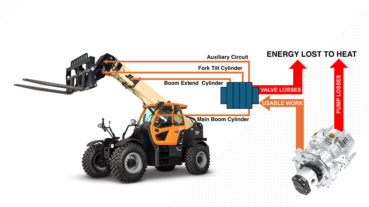
Looking back at the aforementioned telehandler example, simply splitting the main pump from the steering is a good start, but we need to go a little deeper. One path we have here is the use of an electronic load sense circuit. This method allows for keeping the existing valve bank and maintaining the same control logic for operating the valves. The variable displacement pump is then replaced with a fixed displacement pump. Rather than varying the displacement of the pump mechanically, the motor varies rpm to match flow demand. How does the motor know what the flow demand is? The same way that the load sense piston pump did. We’re going to compare the pressure at the load sense line of the valve bank and the inlet to the valve bank, and the motor is going to vary rpm to maintain a setpoint. This may sound complicated, but there are companies like Terzo Power Systems that have a plug-and-play motor, controller, and pump package with everything needed for this built-in.
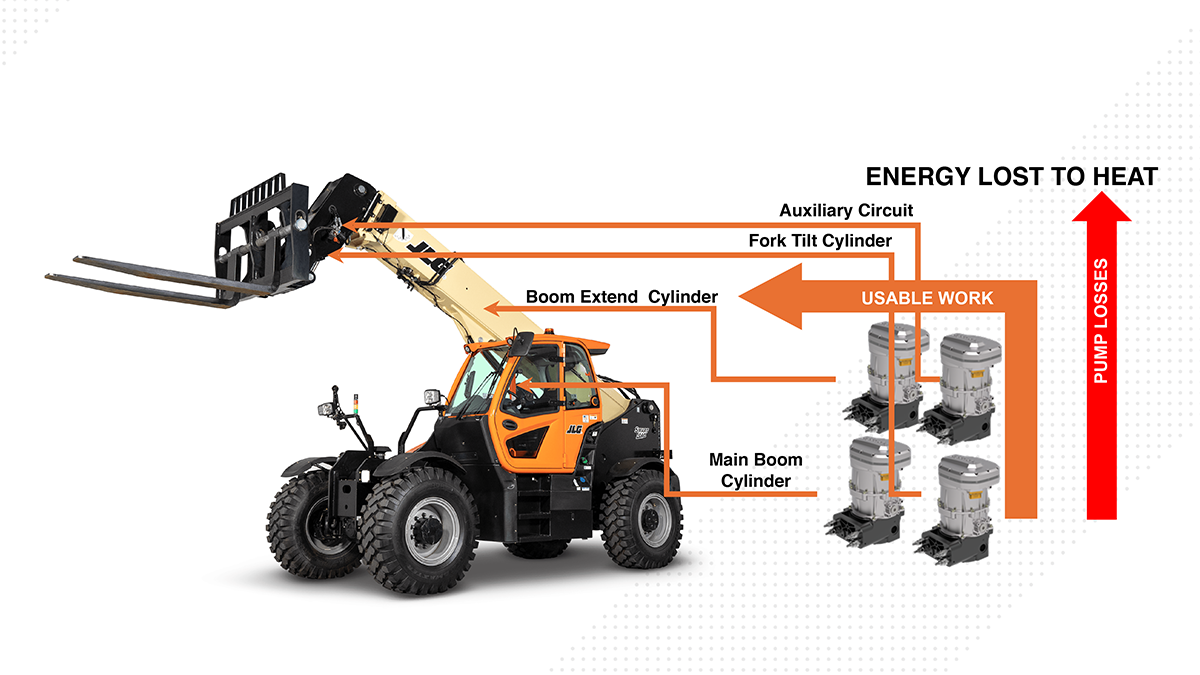
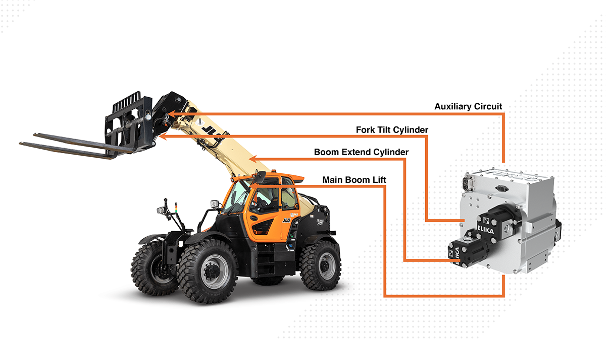
The next example is a little bit harder to sell, even though it offers the most potential for efficiency gains and system simplification. A distributed hydraulic system explores each function and matches a hydraulic power unit with the needs of that actuator. This might sound unorthodox, thinking of the size of traditional induction motors. With the power density we’re seeing in newer motor and controller technologies used in BEV, this is much more feasible. How does it work? The idea is similar to how an electro-mechanical actuator works. A servo motor is coupled to a ball screw that turns clockwise or counterclockwise to extend or retract the cylinder. Instead of a ball screw, a bi-directional hydraulic pump is attached to a servo motor that is plumbed to the cylinder. If the motor spins in one direction, the cylinder extends; if it spins in the other direction, the cylinder retracts. Why do this instead of just using an electromechanical actuator? This allows the equipment manufacturer to maintain the same actuators that have taken decades to perfect, as well as maintain the resilience to shock loading that hydraulics offers. Simple float functions are still an option, and many other inherent benefits to hydraulics remain while capturing a large portion of the efficiencies gained from the electromechanical actuators.
The other aspect of “why” lies in the serviceability. If you’ve ever had to troubleshoot an issue in a large valve bank, you know this is not easy and can lead to ample downtime. Imagine if that valve bank didn’t exist, and instead, you have a telehandler with 4-5 motor pump units cleverly integrated onto or into the reservoir. Now, you’ll be able to directly go to that motor pump unit, visually see the status, or read any trouble codes over CAN, then replace that motor pump unit with simple connection points for any function that seems to be having an issue. Also, to take it to the next level with these high-end motors and controllers, we can monitor parameters including the average number of rotations required to go from point to point on an actuator. A large change in this number over time indicates a need to schedule maintenance.
The transition to BEV in Hydraulics should be regarded as a welcome challenge, it opens up all kinds of interesting possibilities, and if the system is utilized correctly, its performance will bring value to the added cost over time.


