Identifying Pressure Relief Valve Symbols
Elements of image furnished by Adobe Stock | Anatthaphon
Hydraulic components are illustrated using both simplified and detailed symbols. Simplified symbols show the function of the component, whereas detailed symbols show internal connections and how the component operates. If two or more functions are enclosed within one component, for example a pressure relief valve with a reverse flow check valve, both functions are drawn within an enclosure. Enclosures can be identified by a thin line around the component, interrupted by a dash (Refer to Fig. 10-6B).
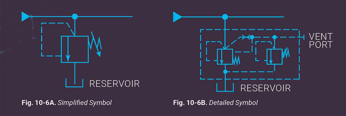
Figure 10-6A illustrates the simplified and Fig. 10-6B the detailed symbols for a compound (pilot operated) pressure relief valve. The simplified symbol indicates that pilot pressure acts against the piston or spool element to open the valve when the force overcomes the bias spring and connects the pressure port to drain. The detailed symbol shows how the valve operates internally.
The balanced main spool is on the left, the pilot valve is on the right. System pressure acts on the main spool against the bias spring and, at the same time, through the orifice against the adjustable pilot valve. When pressure is sufficient to unseat the pilot valve, it vents the balanced spool and the valve opens. The valve is “balanced” in that pilot pressure acts on both sides of the balanced spool, preventing it from shifting until the pilot valve directs the vent signal from the bias spring side to drain.
Test Your Skills
1. A compound, balanced piston (or spool) pressure relief valve is balanced by:
A. flow
B. stroke
C. pressure
D. spring force
E. spool size
See Solution
Share this information.
Related Posts


Sponsor

Sponsors