Maximizing Hydraulic System Efficiency
Elements of this image furnished by Adobe Stock; Contributor: animus81
Two Common Ways to Calculate the Appropriate Cooling Capacity Requirement of Hydraulic System
 By Erick Espinosa, Technical Sales Manager, asa Hydraulik of America.
Hydraulic systems play an integral role in numerous industrial, mobile, and many other hydraulic applications, serving as a vital component for a wide array of equipment ranging from a small hydraulic power unit to heavy industrial and mobile pieces of machinery. Despite its advantages, the optimal performance of a hydraulic system hinges on several key factors, one of which is maintaining the hydraulic fluid at the appropriate operating temperatures.

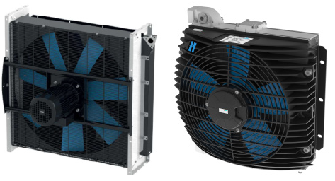
Sample of Hydraulic Systems. Photo courtesy of Hydraulik of America
Hydraulic systems are not 100% efficient due to efficiency losses in various components of the hydraulic system. Typically, pumps and motors have efficiency losses and valves produce regulating losses. These combined losses will produce heat.
It is important to note that for a typical hydraulic fluid with the recommended operating temperature of 40°C (104°F), for every 8°C (14°F) rise in temperature, oil service life may be reduced by 50%. Due to atmospheric pressure, typically hydraulic fluid may contain up to 9% air at 20°C (68°F), and at 60°C (140°F), this air content may increase to 14% leading to potential cavitation.
The hydraulic fluid’s operating temperature is important as it directly influences its viscosity, lubricating properties, and overall effectiveness within the system.
Maximum and Minimum Oil Viscosity Recommended by Pump and Motor Manufacturers
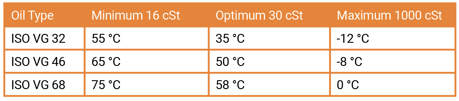
- V min. 8-10 cSt short period in discharge line
- V max. 1.000 cSt short period in suction line
- Optimum operating viscosity
- V optimum ~ 30 cSt (pump performance is
generally estimated at 30 cSt)
- V optimum ~ 30 cSt (pump performance is
Maximum and Minimum Oil Viscosity Recommended by Pump and Motor Manufacturers
Fluctuations in temperature can lead to viscosity changes, affecting the fluid’s ability to flow smoothly and lubricate components properly. This, in turn, can result in cavitation, leakage, increased wear and tear on system components, and potential system failures.
Where is heat generated?
Understanding the intricacies of hydraulic system heat generation is critical for maintaining the efficiency of the hydraulic machinery. Heat generation within a hydraulic system is a consequence of the conversion of mechanical energy into thermal energy as the hydraulic fluid circulates through the system. This process occurs due to several contributing factors, each playing a significant role in the overall heat generation process.
Fluid friction, one of the primary contributors to heat generation, occurs as hydraulic fluid encounters resistance while flowing through the system. This resistance is caused by the interaction between the fluid and internal components such as valves, hoses, fittings, and the surfaces of tubes or cylinders. The energy expended to overcome this friction is converted into heat, gradually raising the temperature of the hydraulic fluid and the surrounding components.
Pressure changes within the hydraulic system also contribute to heat generation. When the system experiences rapid changes in pressure, such as during pump operation or valve manipulation, the hydraulic fluid undergoes adiabatic compression or expansion. This compression and expansion process increases the fluid’s temperature, further contributing to heat generation within the system.
Furthermore, the efficiency of hydraulic components themselves can impact heat generation. Inefficient components, such as pumps, motors, and valves, may generate excess heat due to internal losses resulting from friction, leakage, or inefficient fluid displacement. These inefficiencies not only reduce the overall efficiency of the hydraulic system but also contribute to increased heat generation, potentially leading to accelerated wear and reduced component lifespan.
External factors, such as environmental conditions, also play a role in heat generation within hydraulic systems. High ambient temperatures, exposure to direct sunlight, or inadequate ventilation can elevate the temperature of the hydraulic fluid and components, aggravating heat generation and potentially compromising system performance and reliability.

Sample of Hydraulic Systems. Photo courtesy of Hydraulik of America
How to determine the cooling capacity?
To solve this important aspect of hydraulic system operation, we will discuss the two common ways of determining the cooling capacity required to maintain optimal operating temperature. By understanding the factors influencing temperature regulation and calculating its cooling requirement, we can now find ways to implement an effective cooling solution. With this, we can enhance the efficiency, reliability, and uptime of hydraulic systems.
With the knowledge of the factors that generate heat in a hydraulic system, we should now focus on how much cooling is required to mitigate this temperature surge.
In a hydraulic system, the formula for calculating the heat rejection requirement can be expressed as:
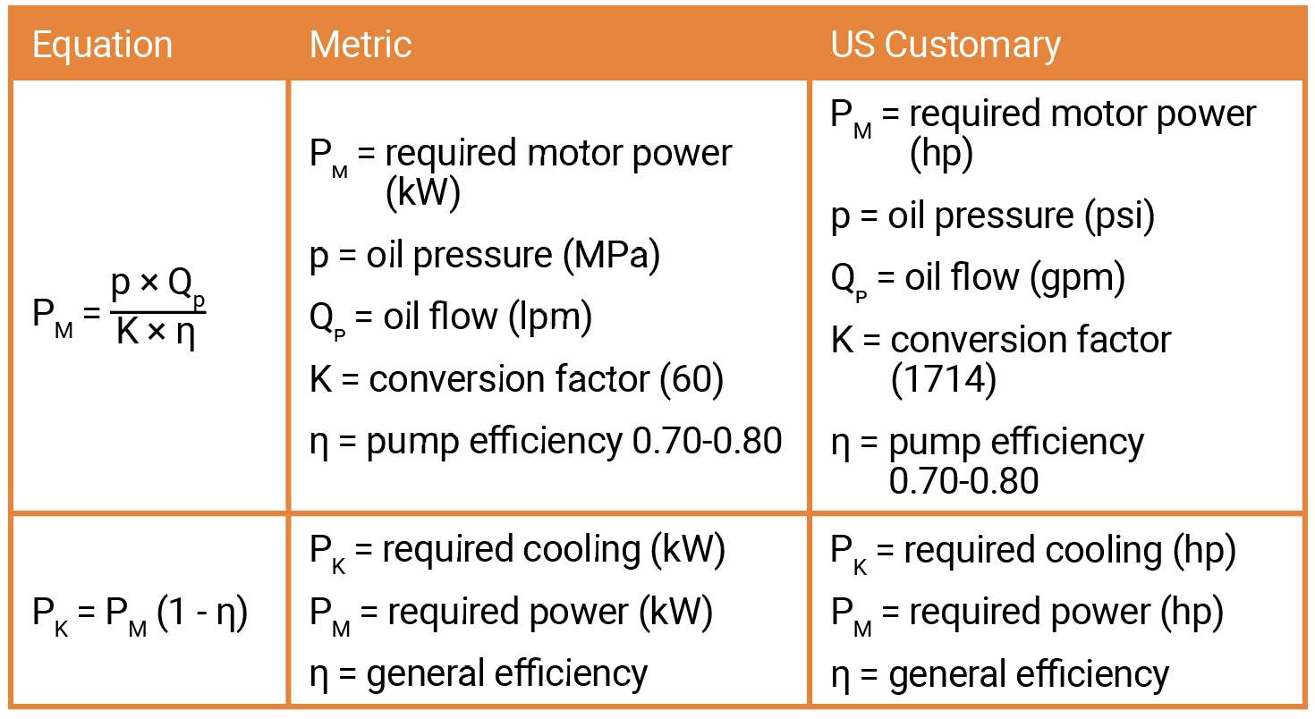
Hydraulic system with constant pumps has a general efficiency from approximately 70-75%. η = 0.7 to 0.75 / circuits with variable pumps: η = 0.75 to 0.80.
For the hydraulic system to be effective, we should maintain thermal balance within the system. This means the heat dissipated is equivalent to the heat generated.

Thermal Balance Heat Balance is achieved eventually when oil temperature equalizes with ambient air temperature. But at what temperature?
The cooling capacity requirement can be determined through various methods; below are two of the most common ways to calculate cooling capacity, each offering unique insights into system optimization.

Sample of Hydraulic Systems. Photo courtesy of Hydraulik of America
“Installed Power Method”
Calculating the cooling capacity by this method is the most common way of determining the requirement. This method can be used for newly designed systems or an existing system.
In this method, a percentage of installed power is considered to produce losses that will generate heat. This percentage depends on the system and how complex it is, and the losses could be anywhere from 25% to 50%. The most common rule of thumb is about 1/3 (33%) of installed power is considered a cooling capacity requirement. Installed power in a system is the primary electric motor(s) power rating.
A percentage of the above-installed power (25%-35%) is then assumed to be the system inefficiency that is converted into heat that needs to be dissipated.
For example; we have an installed power of (PM) 40kW (54 hp) and an assumed system inefficiency of (η) 33%; we can determine the required cooling performance (PK);
First, we assumed 1−η to be 33% = 0.33
Next, we multiply the required motor power by this result:
PK = 40 kW × 0.33 = 13.2 (54 hp x 0.33 = 17.8 hp)
Therefore, the required cooling performance is 13.2 kW (17.8 hp). This means that to maintain the system’s optimal operating temperature, a cooling capacity of 13.2 kW (17.8 hp) is required to dissipate the excess heat generated by the 40 kW (54 hp) system with an inefficiency of 33%.
“Field Testing Method”
The “Field Testing or Warm-Up Method” is the most accurate way of measuring the heat losses for an existing hydraulic system. This method involves running the hydraulic system at maximum load for a specified period while monitoring various parameters to calculate the amount of heat generated.
This test must be conducted ideally when the system is shut down for several hours allowing the hydraulic fluid in the tank to reach ambient temperature. Any existing heat exchanger in the system must be isolated or turned off before this test. The total hydraulic fluid volume must be recorded. If the fluid is anything different than standard hydraulic fluid, we need to consider that in our calculation since the specific heat and density may be different which could lead to different results in the heat load calculation.
Next, we should identify the Maximum Load: Determine the maximum load that the hydraulic system will undergo during operation. This will be considered using different factors, either by the maximum pressure, flow rate, or a combination of both, depending on the application. This test must be conducted at maximum load to ensure we collect data based on the worst-case scenario.
Install sensors and monitoring equipment to measure the following parameters:
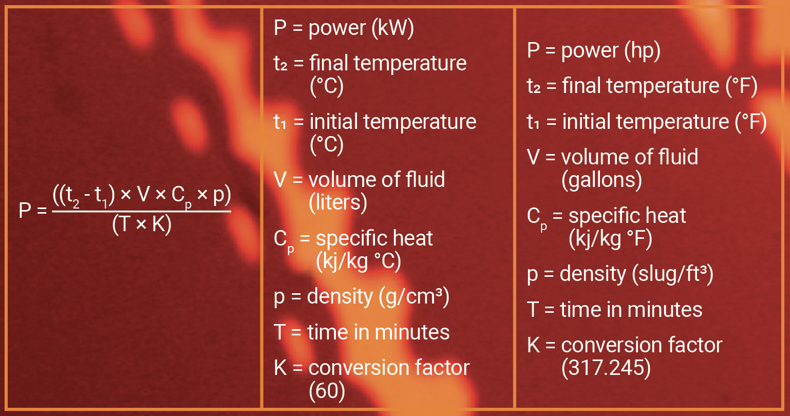
- Hydraulic fluid temperature before start-up. °C (°F). (t1)
- Hydraulic fluid temperature at the end of the test °C (°F) (t2)
- Volume of the hydraulic fluid in Liters (gallons) (V)
- Specific Heat Capacity of the Hydraulic Fluid kJ/kg °C (°F) (cp)
- Density of the Fluid g/cm³ (slug/ft³) (ρ)
- Time elapsed in minutes (T)
Start the Warm-Up Process: Operate the system first at a lower pressure and flow. This will give time for the hydraulic fluid to circulate through the whole system. Next, slowly increase the load until it reaches the identified maximum load. Run the hydraulic equipment normally including maximum load conditions for the specified time. This period should be long enough to allow the system to reach a steady-state temperature but not too long to risk overheating components. We should avoid letting a quick temperature surge as too much heat can damage components of our hydraulic system. Typically, 30 minutes to 1 hour is sufficient, but it can vary depending on the size and complexity of the system.
Monitor Parameters: Continuously monitor the parameters mentioned above throughout the warm-up period. Record the data at regular intervals to capture any changes over time.
Calculate Cooling Power: Use the recorded data to calculate the heat generated by the hydraulic system using the following formula.
These are the two common ways we can determine the heat generated by our hydraulic system. Once this is calculated, this information is used as the cooling requirement.
Thermal Management Technologies
Hydraulic systems employ a blend of passive and active cooling techniques to manage heat generated due to losses. Passive cooling involves oversizing the tank capacity to store large volumes of fluid and counting on heat dissipation through tank walls entirely by radiation. This method is not cost-effective and efficient since it depends on the size of the tank and atmospheric temperature. A larger tank with a larger volume of fluid than necessary is required to maximize the cooling through the radiant surface area of the steel tank. The heat dissipation efficiency also depends on the temperature difference between the hot oil in the tank and the atmospheric temperature. Active cooling involves a heat exchanger that utilizes a cooling media such as water or ambient air to cool the fluid. While both methods play crucial roles, heat exchangers stand out as particularly efficient solutions. They utilize airflow or cold water and heat exchange principles to dissipate heat effectively. Heat exchangers boast exceptional efficiency by maximizing surface area contact between cooling media such as air or water and hot oil. This efficiency ensures optimal heat transfer, contributing significantly to the overall cooling process.
Air/oil heat exchangers offer several advantages, including lower operating costs, ease of maintenance, absence of oil contamination, reduced risk of corrosion, and lower installation expenses. They are typically more affordable to operate and maintain compared to water/oil heat exchangers. Additionally, they do not require as much space and can function in environments with clean ambient air without the need for ventilation. However, they have some drawbacks, such as being more expensive initially than water/oil heat exchangers, generating noise, and their performance is sensitive to fluctuations in ambient air temperature.
On the other hand, water/oil heat exchangers have their own set of advantages, such as being smaller in size, operating quietly, maintaining low-temperature variations, and the possibility of reutilizing heated water. They also eliminate the risk of emitting heat into the atmosphere and provide consistent performance regardless of ambient air temperature. However, they come with some disadvantages, including higher installation costs, the need for a clean water supply, the risk of corrosion, and potential contamination issues. Additionally, they require the cost of water usage, which can add to operational expenses.
Heat exchangers offer versatility, adapting seamlessly to various environments and operating conditions. Their reliability and effectiveness make them indispensable components in hydraulic systems, enhancing performance and longevity. In summary, while both passive and active cooling methods play vital roles, heat exchangers emerge as indispensable assets, offering unparalleled efficiency and reliability in managing excess heat within hydraulic systems.
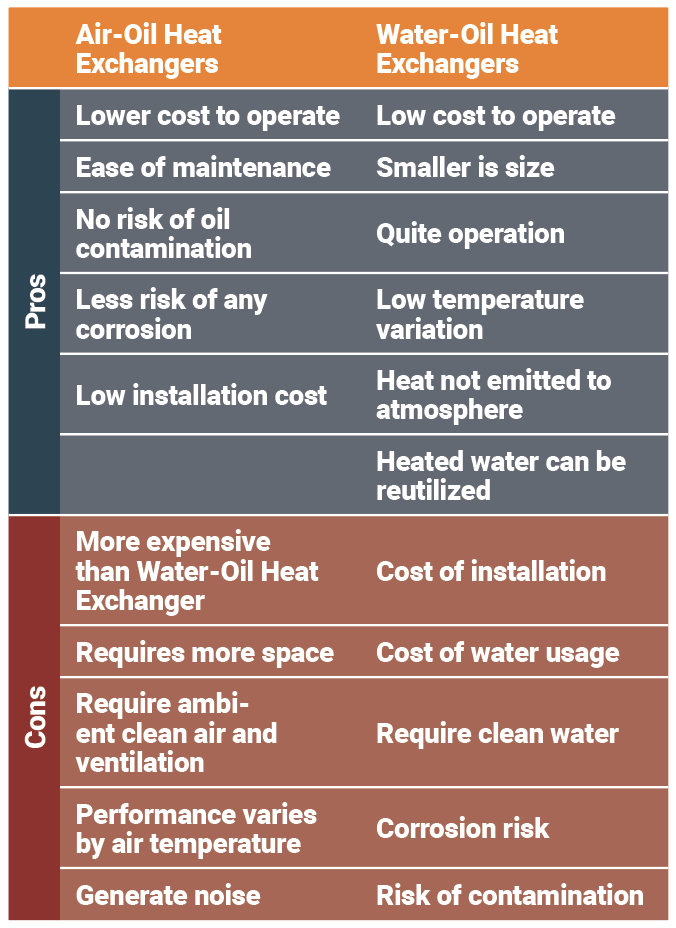
Sample of water/oil exchangers. Photography courtesy of Hydraulik of America
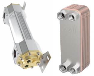
Sample of air/oil exchangers. Photography courtesy of Hydraulik of America
Hydraulic systems continue to evolve with advancements in technology and innovation, and new materials, innovative designs, and cooling techniques may emerge to address the evolving demands of modern hydraulic applications. By staying abreast of these developments and adapting cooling strategies accordingly, we can maximize the performance and reliability of hydraulic systems while minimizing downtime and maintenance costs.
Share this information.
Related Posts


Sponsor

Sponsors