Securing Aerospace & Military Hydraulic System Finishing
Hydraulic functions are critical in scenarios where failure is not an option, such as in jet fighter flaps, moving tails, or missile launch systems. Any hydraulic failure in these situations would be unacceptable.
As hydraulic systems become more complex, the tolerances for components have become stricter, leading to numerous intersecting holes and edges that can be potential failure points. To mitigate human error, selecting the best finishing method for critical components is essential.
Some finishing methods stand out due to their numerous benefits and reliability. These methods include Electrochemical Machining (ECM), Thermal Energy Method (TEM), and Abrasive Flow Machining (AFM). ECM uses electrical and chemical processes to remove material, TEM uses thermal energy for deburring and cleaning, and AFM uses a pressurized abrasive medium to smooth surfaces and edges.
After reading this article, you will understand the capabilities of these methods, where they are most effective, and their advantages and disadvantages. Before delving into the three technologies, it’s important to address the risks associated with burrs.
What does Burr mean?
Nobody wants burrs. Even with tremendous efforts into design, process planning, and manufacturing, it is hard to ensure that finished parts are completely free from burrs consistently.
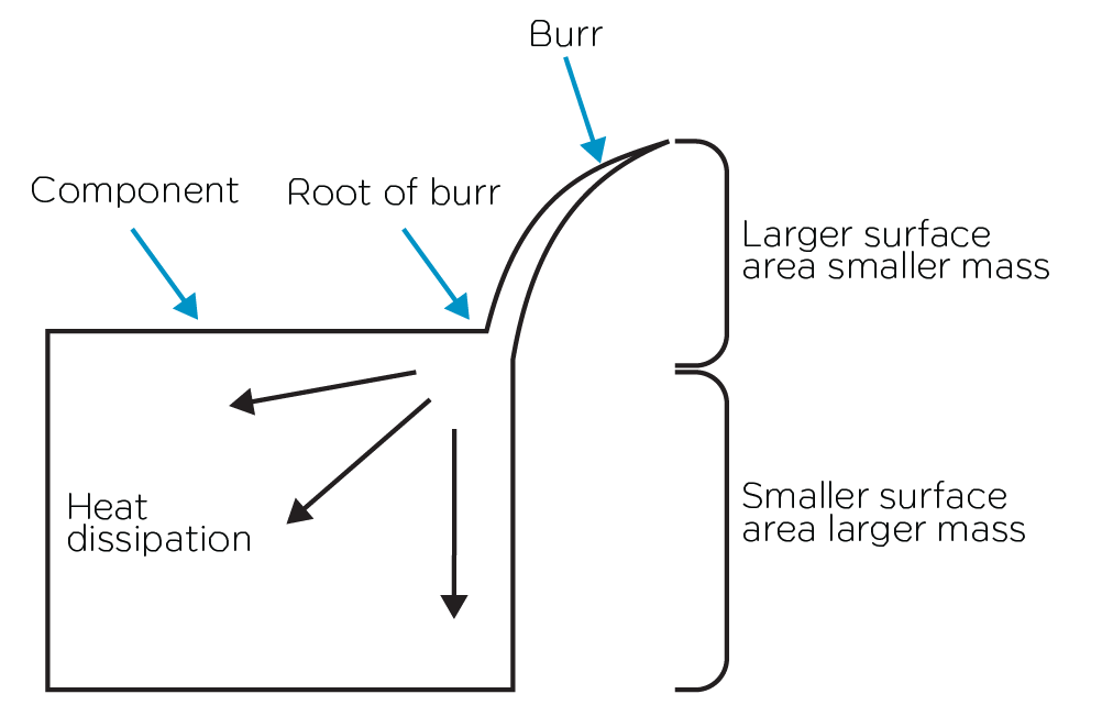
Burrs can compromise the design integrity of a part, necessitate additional processes to fix, create safety hazards, and lead to product malfunctions. This results in extra costs, re-manufacturing, warranty claims, service issues, and recalls, not to mention potential damage to the company’s reputation. It is crucial to remove or secure burrs to prevent them from detaching from the part. The characterization of a burr depends on how strongly it is attached to the workpiece material, with the sharpness of the burr being a critical criterion for safety concerns.
Burrs Impact in Fluidic Systems
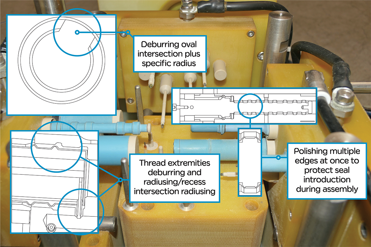
It starts with the assembly of components. The hydraulic function involves the smooth motion of elements like the spool in the bushes (sleeve) and sealing. Mounting seals in intricate bores is a critical operation. Typically, specific tooling helps position the seals correctly, but if a seal encounters a sharp edge or a burr, it can be damaged. Such damage might go unnoticed until a leak occurs, which could happen long after the testing phase, such as when an aircraft is in flight or a rocket is supposed to fire.
Today, fluid power is at the heart of many critical areas. It’s present in some of the most challenging tasks – trigger, control, maneuver, lift, brake, steer, adjust, and many more. At the same time, the demand for higher power, faster response, finer control, and compact sizes has driven modern-day fluid power toward higher operating pressures, intricate designs, and compact dimensions.
Aerospace is at the forefront of this trend because weight is a critical factor. The industry is driven by the need to pack as much functionality as possible into the minimum space and weight. A hydraulic failure could be devastating and potentially life-threatening in most aerospace and defense applications.
ECM is the Selective Deburring Method Under a Minute
ECM is ideally suited for Aerospace’s hydraulic aluminum manifolds. It’s a selective process, meaning you can decide which areas to process. In addition, you can process several regions in different locations at once and choose what kind of machining, deburring, edge shaping, polishing, or structuring you would like to apply to these targeted areas.
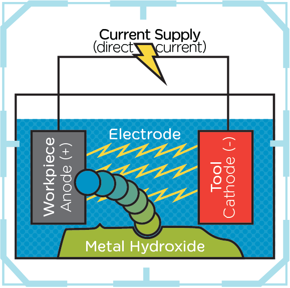
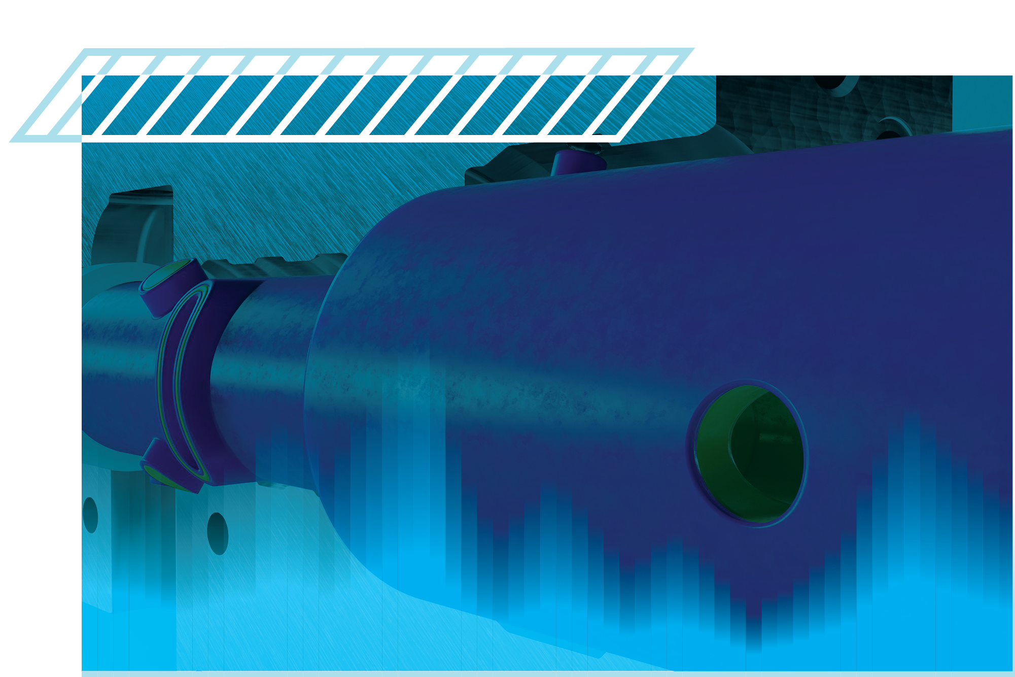
Electrolytic machining (ECM) is a subtractive method operating on the principle of anodic metal dissolution via an external DC power source.
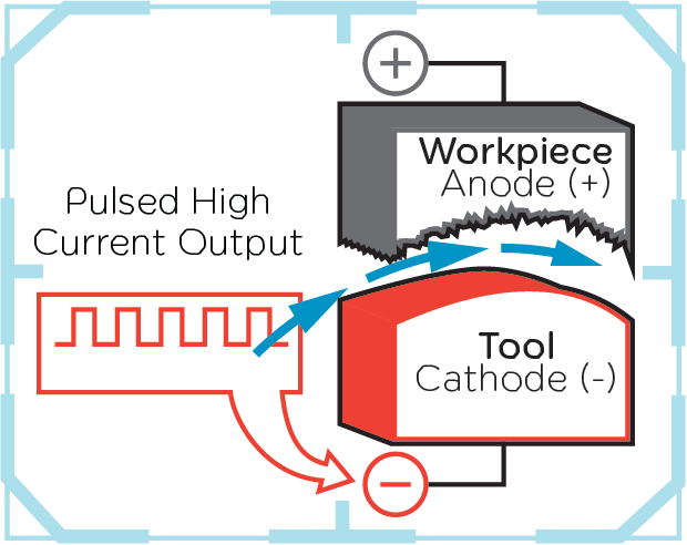
One of the critical features of ECM is that there’s no contact between the tool (-) and the workpiece (+). The shape of the tool cathode determines the shape of the material removal. ECM is an imaging method. Extrude Hone uses insulating material where no work is needed, leaving the conductive material visible in areas where the material removal process occurs. Due to the use of a cathode, the electrochemical process comes without physical contact, applying zero stress to the components. The geometry is perfectly under control and the tool experiences minor electrical wear, but none mechanically. The cathode is consumable.
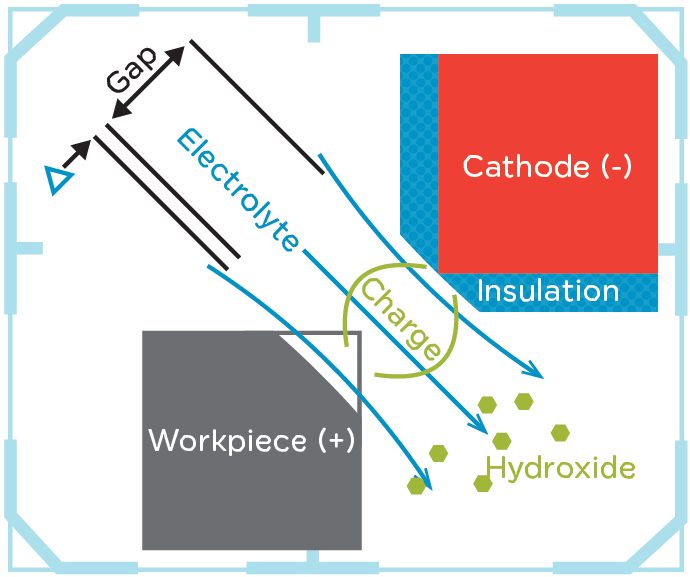
The final shape accuracy depends on the cathode design and the machining precision.
An electrolyte solution (NaCl or NaNO3) handles charge transfer in the working gap to allow the dissolution. The resulting electron current releases metal ions from the workpiece. The removed material comes as hydroxide and is rinsed out of the gap by the electrolyte flow. Then, it must be removed from the electrolyte by an appropriate separating device. Extrude Hone’s process uses a large chamber filter press to ensure a clean electrolyte returns to the machine.
The ECM process provides quality and productivity, surpassing conventional capabilities.
ECM Variations
The most common iteration is Static ECM, in which the cathode moves once from its standby position to the working position before the current is applied while the cathode does not move. A single cathode can include multiple areas of different geometries to process several locations simultaneously. When the cycle is over, the cathode recesses to the standby position to enable the part to be released.
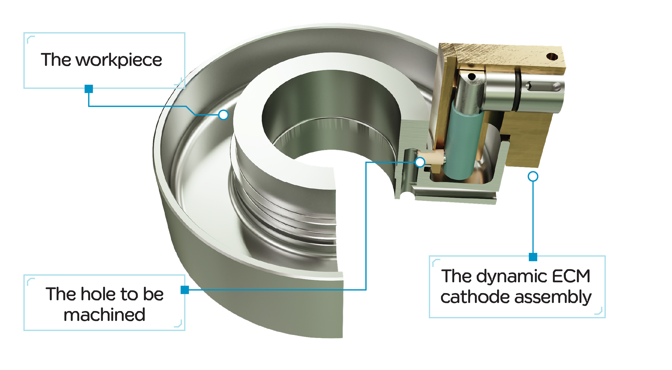
In the Dynamic ECM, the current applies while the cathode is moving. Usually, the cathode is attached to a single or dual NC-controlled axis to allow sophisticated, exact motion. This method is use in EC Rifling to create a twisted groove inside a gun barrel or to drill a hole behind a wall that direct conventional drilling could not reach.
Finally, we come to the process of micro-structuring ECM. Suppose you need to machine various internal or external patterns, like radial and axial structures. In that case, you must do it with high accuracy and repeatability—micro structuring benefits compressors, heat pumps, refrigeration, air bearings, or clean gas applications. ECM offers a solution to deliver productivity gains and an attractive cost per part for all these variations.
ECM Process steps
- The components are loaded into the ECM open fixture. The top side of the fixture is then closed on the bottom one, surrounding the part.
- The electrolyte starts to flow; The short circuit test takes place before applying the total current.
- Full current runs, controlled by cathode or cathode groups.
- Burrs are dissolved, edges are rounded, shaped, and structure applied.
- The cycle finishes, and the fixture opens.
- The component is unloaded
ECM Applications Sweet Spot
As previously mentioned, ECM is ideal for conductive materials, including those that are hard to machine. It excels in processing targeted areas, even those that are difficult to reach, with precise control and high productivity. Many hydraulic components meet these criteria. The average cycle time for ECM is usually under a minute, and for simple applications, multiple parts can be processed simultaneously in a multi-fold fixture.
A Few Words about Post-Treatment
A two-post-process step operation, including electrolyte rinsing and passivation, usually follows ECM machining. Simple dunking stations are the most common, but it goes up to multiple automated stations with advanced cleaning features like ultrasonic.
Electrochemical Machining benefits
- Design accuracy.
- Stress riser removal.
- Enhanced component longevity.
- Process efficiency.
- Deburring precision.
- Increased productivity.
- Quality and repeatability.
ECM Case Studies: An Aerospace Manifold
Let’s focus on an Aerospace manifold, precisely one from Dassault Aviation, that goes in a Falcon jet. That’s 248 (yes, no typo, two hundred forty eight) areas processed in 5 minutes in a 3-step process. The ECM technology allows the design of complex fixtures; in that case, one advanced fixture per step. The machine can be a single, dual, or triple station, depending on how you want to organize the production. The limit will be the current available, which depends on the total surface to be processed. Remember, for example, that an intersected hole surface is an oval ring that contributes to limiting the surface.
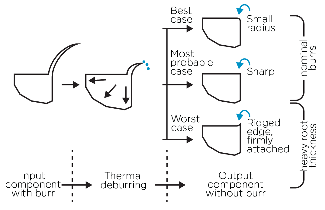
Remove burrs in the blink of an eye with Thermal Deburring
TEM can accommodate one of Aerospace’s most common hydraulic manifold materials, aluminum. Thermal Deburring can take away burrs by generating a super heat wave, reaching 3,300°C (6,000°F) in just a few milliseconds. TEM is suitable for that material because it is that fast, and the pressure is much lower with aluminum. Imagine TEM at shallow pressure can remove burrs from plastics.
Nevertheless, with aluminum, some critical points must be assessed when dealing with aluminum components. Do you have some walls, structure, or specific areas of your components, like small lips that are very thin? If this is the case, there is a need to pay some special attention.
As in thermal deburring, we deal with a combination of hot temperature and the force of a heat wave. If the part is fragile by nature, the fixturing will ensure the best part orientation and maintain it firmly to take the best out of the heat wave, avoiding potential deformation. Your part includes some tricky designs with thin material; if the orientation and fixture leave too much energy, some inserts can physically protect the most fragile regions.
That could sound overwhelming to those unfamiliar with the process, but it’s the best way to avoid deformation and damage and make the most of a deburring cycle that will last less than a minute.
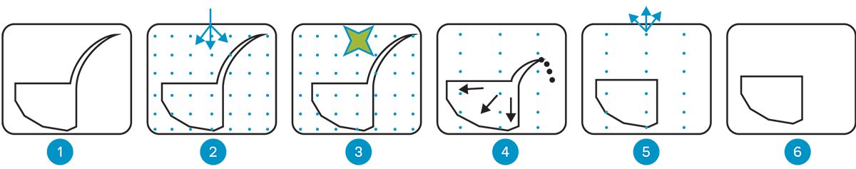
TEM Process steps
- Loading of the components into the TEM chamber. The chamber is closed.
- The chamber is filled with a pressurized mixture of gases.
- Gas is ignited
- Burrs are oxidized, and the component deburred.
- The chamber is vented to de-pressurize
- The chamber opens, and the component is unloaded
TEM applications sweet spot
Because a gas envelops the part and goes deeply into it, the circular deburring requirement with no specific edge tolerances is perfect for the TEM process capability. When you need to remove all burrs and particles, TEM can ensure quality and productivity. Please note that fixture design comes into play, allowing multiple parts to be processed simultaneously to increase productivity drastically.
A few words about post-treatment
Aluminum loses its brilliance during the TEM process. A suitable post-cleaning agent can restore its shiny appearance.
For other materials, no worries too. A cleaning operation will remove the TEM oxide by-product. Chemical market leaders in cleaning and degreasing offer a range of post-cleaning products designed to address the different materials.
These products are utilized in post-treatment stations typically used for cleaning and passivation. The equipment starts with straightforward dunking stations and goes up to multiple automated stations with advanced cleaning features like ultrasonic.
Thermal Deburring benefits
The first benefit of that technology is speed. Because the burrs or flashings are much smaller than the component, they reach their auto-ignition point instantly. The burrs oxidize in the oxygen-rich chamber without any harmful impact on the element.
The second benefit of that technology is integrity. Compared to manual deburring, you have the insurance that the deburring operation will run without further inspection. That’s reliability. In addition, you remove the burden of finding skilled labor by relying on a machine. You are a perfectionist; the machine can be automatically loaded and unloaded.
The third benefit of that technology is low cost per part. For more insights about the thermal deburring process and how it compares to the other technologies, we recommend reading the Fluid Power article: Small Burrs Create Significant Problems from the May 2024 edition.
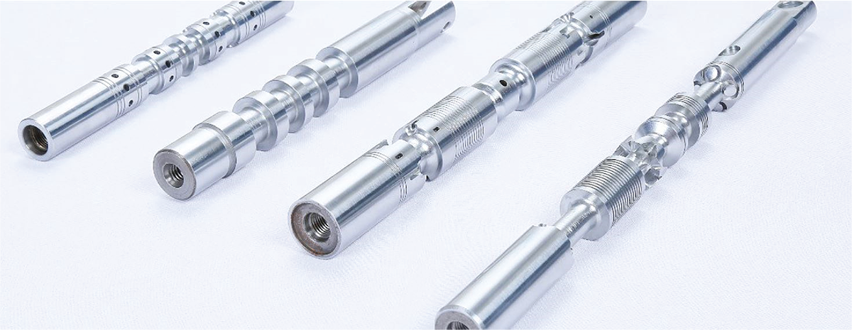
TEM Case Studies: Spools
Let’s focus on one critical component that plays a massive role in hydraulic systems: a high-precision turned part, the spool. Spool manufacturing means high volume with tight tolerances that match stringent standards of quality. It comes with plenty of areas with burrs; manual deburring would be tedious and risky, and other finishing processes usually take too long. One solution is to use TEM to deliver 100% accuracy in burr removal by removing all burrs from all edges, threads, breakthroughs, and inner intersected holes.
AFM – The Abrasive Media flow for surface enhancement, deburring, and flow tuning
AFM (Abrasive Flow Machining) was born to address the need to polish flow paths. A viscous-elastic, non-Newtonian media loaded with abrasive grits is pushed back and forth through the passages. Under pressure, the grits will naturally be forced on the external surface, which means that higher pressure means better cutting impact. A passage can be a natural channel (e.g., a manifold) or artificially created by enclosing a part in a fixture (e.g., an impeller). A hole in a manifold is a natural geometry, while for open impellers, the fixture will create a gap between the part surface and the wall fixture.
The fixture’s purpose is also to handle the part or multiple parts and to guide the media toward the working areas.
In addition to this, multiple parameters come into play. For the fixture design, you must decide on the gap dimension, control the restriction, and the cutting impact. Regarding the media itself, the media recipe encompasses the polymer type and viscosity, the nature of the abrasive grits (aluminum carbide, boron carbide, and diamond being the most common), the grit size, and the density of the abrasive in the mix. But that’s not all; the process parameters, the extruded volume of media, the media flow rate, pressure, and the media temperature range will have to be decided and controlled.
Each application is unique, and knowledge plays a huge role. It’s essential to work with experts who, in addition to building equipment, designing and mixing their media, and running parts in contract shops, have decades of experience and a massive knowledge base.
AFM immediately found its markets in extrusion die polishing, complex automotive intakes and exhausts, and aerospace components that require polishing in the final fluid flow direction.
Hydraulics came rapidly after entering the picture, first with closed impellers, valve bodies, and manifolds made of exotic materials. Today, in hydraulic systems and especially with AM (Additive Manufacturing) components full of organic channels, the AFM thrives in delivering its process edge by nature.
But that’s not all about surface improvement. When flowing along a surface, any restriction will see more intense cutting action, so change in the direction, edges will be the target of choice for the media, delivering deburring (up to 0.2mm or 0.08 inches) and edge radiusing. The AFM process will clean up the edge from the burrs, even micro-burrs, remove stress risers, and eventually create specific shapes. A good illustration is using AFM for turbine disk blade slot edge rounding. Another excellent application is the deburring and radiusing of intersected holes in a titanium manifold.
The AFM process provides quality and productivity, surpassing some conventional capabilities.
AFM Variations
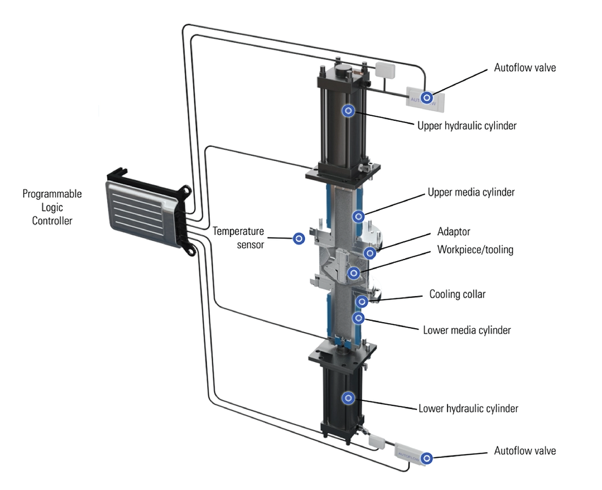
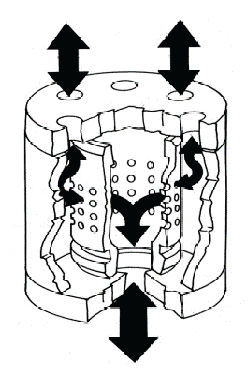
The most common is Two Ways Flow AFM, in which a machine includes two opposite media cylinders that actuate a volume of media, pushing it through the tooling that handles the part and guiding it toward the working areas.
In the One-Way flow AFM, the media is continuously pushed in the same direction through the part before falling on a table and then within a replenishment media cylinder; this configuration fits applications where a massive volume of media is needed, like in hot runners’ blocks or large pump impellers.
Finally, MICROFLOW. If you want the AFM benefit for small holes, MICROFLOW is one solution to address flow tuning down to 40µm (1,575 micro inches) orifices, way below what we find in Aerospace. Think about nozzles, spray holes, and any flow restriction calibrated holes. MICROFLOW is capable of micro-deburring and polishing the surface without damaging the geometry pattern while applying controlled flow calibration.
AFM Process steps
- The component (s) are (are) loaded into the AFM fixture when required or connected to the media system with hoses for some manifolds. When using a tooling, the fixture’s top side is closed while the machine clamps on it.
- The media starts to flow, filling the empty volumes.
- The process runs with all the HMI monitoring of all parameters.
- Surfaces and edges are polished, rounded, and shaped.
- The cycle finishes, the machine is unclamped, and the fixture opens.
- The component(s) is (are) unloaded
AFM applications sweet spot
With AFM, you decide which surface, channels, and passages to process. Applications requiring flow path surface enhancement for flow rate improvement are good candidates. Components needing flow calibration, such as air, gas, oil, or any other fluid, are suitable applications.
Parts with out-of-reach areas and intricate passages with no line of sight are usually predisposed to benefit from AFM. AFM can also process components made of exotic, hard-to-machine materials. AUTOFLOW is the most advanced control of the media flow, measuring various process parameters in a close loop system to precisely handle the media flow from both cylinders. It’s ahead of the backpressure feature, the most common first step in improving control over the process.
A few words about post-treatment
Customers’ main question, especially regarding manifolds processed with AFM, is how to ensure the complete removal of the media. First, we conduct a blowing operation after processing that provides 99% media removal. A cleaning operation will then top the process. Depending on the cleanliness requirement, it goes from simple rinsing and cleaning, which is usually good enough, to advanced cleaning operations, including an ultrasonic phase when stringent requirements apply, such as high purity, semiconductor, medical, or injection applications.
Abrasive Flow Machining benefits
- Surface finishes even for
out-of-reach areas. - Enhanced component longevity.
- Process efficiency is under control.
- Extended media life and better cutting force control with AUTOFLOW.
- Increased productivity.
- Quality and repeatability.
AFM MICROFLOW sweet spot: Calibrated Orifices in Aerospace
As said, MICROFLOW is a variation of the AFM process. To better illustrate how it is, consider a nearly liquid polymer media compared to the stiff media from the traditional AFM. Calibrated orifices precisely control fluid flow to accurately guarantee flow rates, pressure spikes, or the amount of fluid in an injection system. In Aerospace, devices with calibrated orifices allow better control of hydraulic movements, providing a smoother and more well-controlled motion, an exact measure of the fuel delivered to an engine. In injection systems, the geometry of the orifices is critical in some cases as it contributes to the quality of the spray pattern. The orifice entrance radius, the absence of deformation within the orifice in addition to the geometry of the orifice, conical or not, will impact the atomization pattern.
MICROFLOW will remove micro burrs at the intersected holes and flow-tune the orifices. If you want to optimize productivity, specific fixtures can process multiple sets of holes simultaneously and eventually different sets with different flow targets within the same part.
For flow tuning applications, especially the ones requiring a high flow lift, MICROFLOW can deliver the perfect orifice finish with a nicely rounded entrance and a nicely polished passage while preserving the exit orifice sharpness. The absence of cavitation with MICROFLOW drastically improves the post-processing outcome.
In Aerospace, for hydraulic applications, the average diameters to calibrate range between 0.5mm (0.02 inches) and 1.5mm (0.06 inches).
AFM Case Studies: Servo valve bushes in Aerospace
Advanced motion control is critical to some aerospace functions. Since the introduction of servo valves in 1951, they have been tremendously improved and continue to be enhanced.
A servo valve must fulfill critical features such as high accuracy, repeatability, and high-frequency response. A closed-loop control is established thanks to the feedback wire attached to the flapper and connected to the spool. While electronics drive the system, hydraulics provide the force. Such a high-quality level also requires a spool/ bushes assembly, which is not the weak point. That’s where AFM comes into play to ensure a perfect finish of the bushes (Sleeve). In a previous section of this article, we saw how spool can benefit from TEM deburring.
Multiple bushes are usually processed simultaneously within an AFM fixture, and the media is flowed through according to the two-way flow principle. As the intersected holes of the bushes/ sleeves are the restrictions, they will benefit the most from the media-cutting impact, first removing any left micro-burrs and then generating a nice micro radius (dimensions directly depend on the cycle time) on both sides of each hole. While the media also flows through the central bore, it will provide a slight cleaning effect without impacting the tolerances.
Wrapping up
The three technologies described in that article, ECM, TEM, and AFM, greatly benefit hydraulic system manufacturing. They enhance finishing capabilities, quality, repeatability, and productivity while removing the human factor. You get the best cost per part while guaranteeing and securing the system’s function into which your components are integrated. On top of that, you do not have to worry about human mistakes and the search for super-skilled labor.
These three technologies satisfy many customers in various industries; what about you?
Share this information.
Related Posts
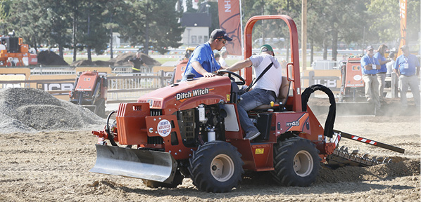
The Kentucky Expo Is Ready For The Demo Expo

Raising the bar: So, You Want to Make a Difference
Thompson Pump Once Again Honored with Prestigious Cigna Well-Being Award, 2nd Year in a Row

Is Your Hydraulic Fluid Contamination Control Strategy Balanced?
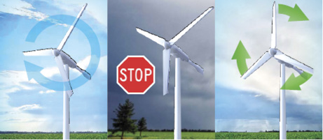
New Safety Brake for Small Wind Turbines

2019 Salary Survey Results
Sponsor

Sponsors