A Vacuum Gripping Approach to Box Palletizing
The following is an opinion article written by Dane Spivak. Its intent is for conceptual purposes only. Contact Dane Spivak by email at dspivak@davasol.com.
Automated palletizing is a shared process among many manufacturing industries where cardboard boxes are picked, placed, and stacked onto pallets to be shipped or warehoused. Vacuum end effectors are often used on the robot arm as they provide a gripping force on the top of the boxes and offer an efficient cost-effective solution. The following article will focus on considerations for vacuum palletizing applications and how to effectively choose vacuum gripping tools.
Before thinking about the gripping tool, it is best to first analyze the box(es) itself. The obvious required information to kick start the project includes the weight and dimensions. Additionally, all possible problematic box features should be understood. The points below may change the design of the vacuum system and tools to compensate for circumstances which are other than ideal.
- What is inside the box? Is it tightly packed or are there loose parts? Is the weight evenly distributed and centered or imbalanced?
- Are there any areas or features on the box which may impact the vacuum grip such as straps, gaps, or known imperfections?
- Is the cardboard corrugated or flat packed? Is it thick and sturdy, or thin and flexible? Is it porous or damaged?
- What is the quality and shape of the box? Is the box new or reused? Is it clean, dirty, tight, bubbled, floppy?
The above parameters are often mistakenly overshadowed by the box weight and dimensions. Most box sizes offer plenty of top surface area to provide substantial lifting forces and safety factors. The challenge is the box conditions, how to design a vacuum solution to grip securely, and maintain a confident hold throughout the robotic transfer process.
Conceptually, the easiest box to grip is a lightweight, tightly packed, new box with high quality cardboard and a clean flat top. It requires little gripping force, is stable on its own, and provides a surface for easy vacuum cup sealing with little clogging or filtration issues. This theoretical box would require a few cups and a relatively low flow vacuum pump or venturi to get the job done. However, real world industrial environments rarely offer such opportunities. Because of that, in many applications, the top surface area of the box would be mostly covered by vacuum cups to offer a sturdy and balanced gripping force. Or in other words, the footprint of the vacuum tool would cover nearly the whole box as shown in Figure1.
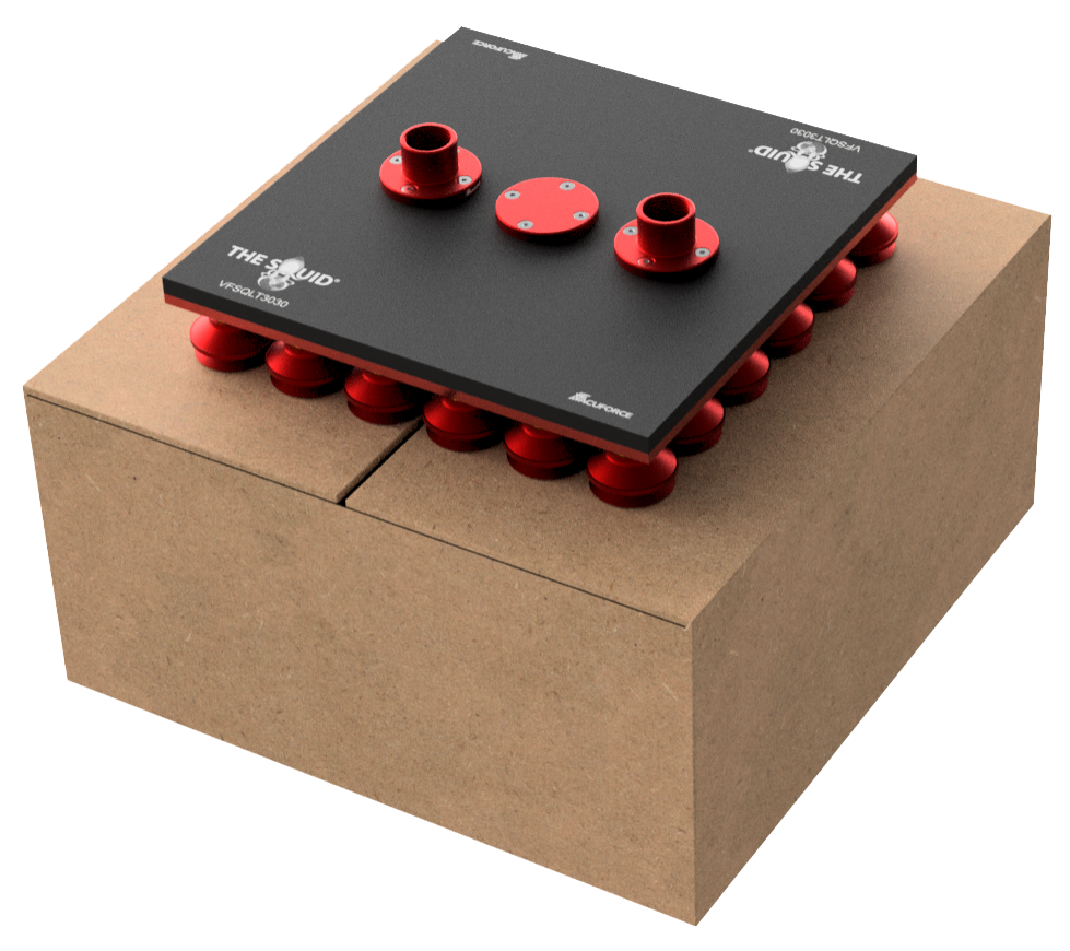
Figure 1 – Vacuum gripping tool box coverage
With a vane pump or venturi, theoretical calculations could suggest the gripping force is overkill. But widespread multiple points of contact across the box is often necessary since the box contents may be unstable, the box itself could sway during movement, or the top surface could deform too much and “bubble”. All these factors could result in instability and cause the vacuum cup grip to peel off and drop the box.
The vacuum cup style and diameter are critical to providing a good seal which does not break. Typically, a single or multiple bellows soft cup is used with a diameter between 1” to 2” as shown in Figure2. These cups offer height and angular compensation and provide cup lip flexibility to conform to the corrugated cardboard surfaces. The cup diameter range is a sweet spot to grip corrugated cardboard well without causing box deformation. Larger cups may initially grip the box well, but, during the lift or transfer the cardboard can deform and cause the cup seal to break and drop the box. Technically, cup diameters smaller than 1” would do the job well too, but it is unnecessary to deal with any more cups than what is needed as more parts can mean more problems and possibly larger pump requirements.
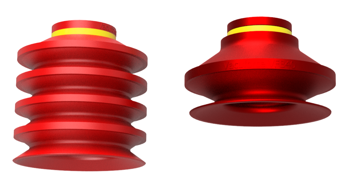
Figure 2 – Single and multiple bellows 2” diameter vacuum cups
Foam vacuum pads can also be used for box palletizing applications as shown in Figure3. The advantage of foam is that it has sponge-like characteristics that allow for good deformation and sealing against corrugated cardboard. It can prove to be advantageous if the box condition is particularly poor and cup sealing is inadequate. However, foam wears out much more often than rubber suction cups, requires frequent replacement, and damage to one area requires replacing the entire foam pad.
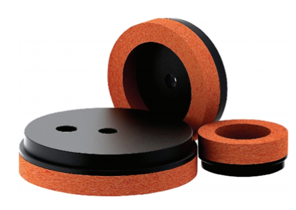
Figure 3 – Foam vacuum pads
Whether it is intentional or not, vacuum cups may not seal against a box, or miss it entirely if multiple box sizes are being picked up. This can happen for a variety of reasons including box gaps, straps, tape, or damage for example. Cups not sealing can cause air to get sucked into the vacuum system which reduces the vacuum level pressure and therefore reduces the gripping force. Unwanted leakage can be controlled or prevented, which is typically done in two ways.
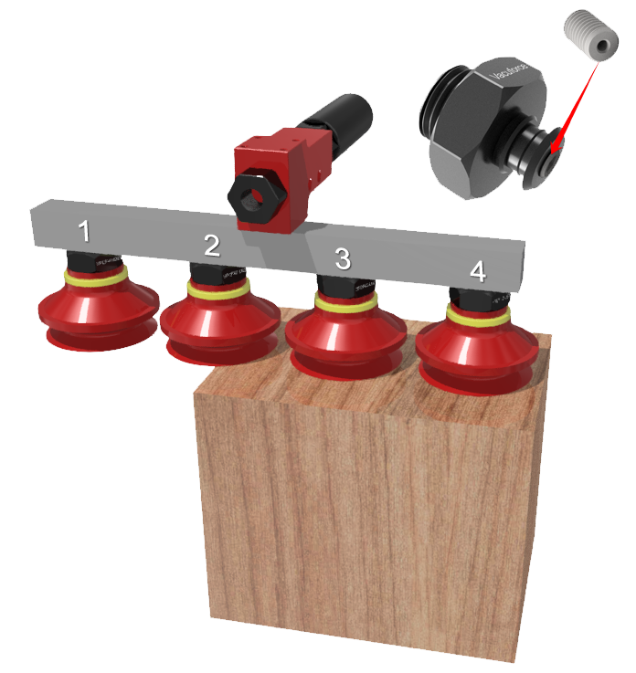
Figure 4 – Orifice screw threaded into a cup assembly and tool
Figure4 shows a cup fitting with an orifice screw inserted. The purpose of the orifice screw is to restrict air flow (leakage) into the vacuum system. Figure4 demonstrates the use of an orifice screw to reduce the fitting diameter though some fittings or tools may have pre-built in orifice sizes for restricting flows. The smallest area or diameter where air passes through controls the maximum volume of air flow entering the vacuum system. Therefore, it is ideal to downsize the restrictive diameter as small as possible to limit unwanted leakage. However, the restrictive orifice should not be infinitely small since flow is required to create a seal for the vacuum cups. Additionally, the orifice should be large enough to allow debris, water, and dust to pass through and collect inside the inline vacuum filter instead of clogging the vacuum line. With that said, the common restrictive orifice diameters are around 1mm to 2mm.
Figure4 illustrates a typical application for using vacuum cups with orifice screws. Cups #1 and #2 are not sealed against the product. The installation of an orifice screw in the cup fittings minimizes leakage and allows a secure grip of the product using cups #3 and #4. It is important to understand the worst-case scenario to allow proper sizing of the vacuum pump or venturi. The tool design and pump sizing heavily rely on the situation where the most cups are exposed to leakage and relatively lower vacuum levels as a result.
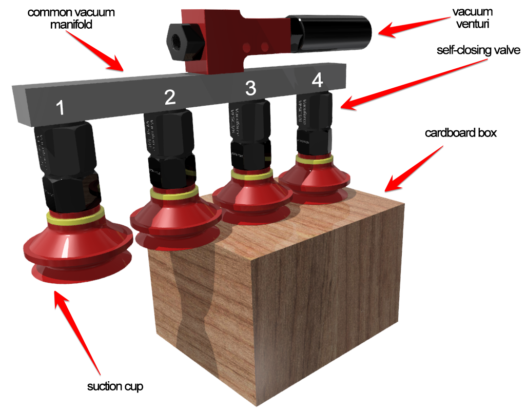
Figure 5 – Self-closing valve tool demonstration
Figure5 shows self-closing valves connected to four vacuum cups with a common venturi as a vacuum source. The vacuum cups, #1 and #2 are not sealed against the box being handled. When vacuum is applied, the self-closing valves on cups #1 and #2 experience an in rush of atmospheric air which closes the valves, isolating these cups from the common system. Cups #3 and #4 are sealed against the box. When the vacuum is turned on, the volume of sealed air between the self-closing valve and the cup face is not large enough to close the valve. Therefore, the self-closing valves remain open allowing vacuum grip against the box surface. When vacuum is turned off, cups #3 and #4 release the box. The self-closing valves attached to cups #1 and #2 return to their open rest position, ready for the next cycle start.
There are different designs for self-closing valves and comparable performing components. Certain designs allow for the bottom seat of the self-closing valve to be adjustable. This feature controls how much flow it takes to close the valve, or in other words, its sensitivity can be adjusted based on the spring tension allowing it to be more versatile. Figure6 illustrates this concept. Other models have no spring at all, and essentially have a free-floating ball. There are also models that use a flexible rubber flap instead of a ball.
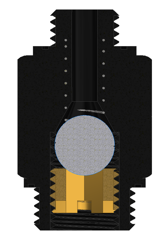
Figure 6 – Adjustable self-closing valve 3D cutaway
Zoning tools can make a major impact on the vacuum system capabilities and pump sizing. Zoning becomes increasingly important when gripping various box sizes or gripping more than one box at a time. Figure7 shows a two-zone tool that grips one or two boxes at a time. Both zones turn on vacuum when gripping two boxes while only one zone turns on when gripping a single box. This allows for high vacuum levels and gripping forces to be achieved when gripping a single box without the use of self-closing valves or orifice screws, which would also typically requires larger pumps. Additionally, if venturis are used on each zone it allows for energy savings as only half the compressed air is being used.
Vacuum pump or venturi sizing can be tricky as it heavily depends on the box condition, vacuum cup size and model, and use of self-closing valves or restrictive orifices. A good rule of thumb is to use a minimum of 1CFM of vacuum flow per 1” to 2” cup, or orifice. This is highly subjective based on the application and vacuum solution. In-house testing can certainly help determine vacuum level and flow requirements, but it is best to seek professional advice from experts and/or the vacuum tool manufacturer to ensure that the correct vacuum source and size is selected. Popular choices for vacuum sources include vane pumps, venturis, and regenerative blowers. Vane pumps and venturis offer high maximum vacuum levels which are attractive with good sealing cups and minimal leakage. Blowers, despite having a relatively lower vacuum level, are chosen when significant leakage is present or for a larger vacuum system as they provide more vacuum flow while using less energy.
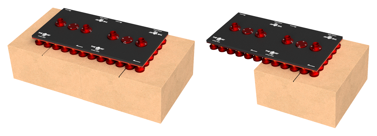
Figure 7 – Two-zone vacuum tool gripping one or two boxes
Vacuum palletizing applications can require attention to detail and critical thinking. But with a solid foundation they prove to offer excellent reliability and repeatability. When considering a vacuum palletizing solution, it is important to consider the box itself, its content, vacuum cup models, leakage flow reduction or prevention, zoning, and vacuum pump sizing. By prioritizing these elements, businesses can optimize their vacuum palletizing applications efficiently to meet the demands of the present-day industrial expectations.
Share this information.
Related Posts


Sponsor

Sponsors