Counter Balance Valves: Part 2
 SIZING FOR CONTROL
In Part 1, I covered the force balance in the counterbalance valve and how to calculate the release pressure. But what happens once the valve starts to open? In this article I will discuss how to size the counterbalance valve to insure stability.
From the previous article we saw that actuator areas, and pilot ratio as well as resistance at the exhaust of the counterbalance valve all influence the release pressure. We saw that when using just an internally piloted valve the release pressure is higher than when using an internally and externally piloted valve. The advantage to using an internally and externally piloted counterbalance valve is that a lower release pressure means a high system efficiency because the pressure to lower the load is less, so the power requirement to lower the load is less.
The preference is therefore to use an internally and externally piloted counterbalance valve for increased system efficiency. The problem that can be encountered with using these counterbalance valves is that if it is not specified properly a stable release pressure cannot be maintained. If the release pressure is not stable, then the valve will open and close erratically (valve chatter) causing load instability.
Once the counterbalance valve opens and the load starts to move there are many factors that influence the stable operation of the counterbalance circuit:
• Counterbalance valve size/flow resistance
• Counterbalance valve pilot ratio
• System motion profile
• The hydraulic stiffness of the circuit
• Mechanical stiffness of the machine
The first two factors are the parameters we need to decide on when selecting a counterbalance valve, and will be the focus of this article. With respect to the other factors the following needs to be kept in mind:
• The speed/motion profile is determined by the application. If acceleration and deceleration can be tuned with some ramping, this will help with load/counterbalance valve stability. Sudden acceleration can cause rapid increases in pressure which could pilot the counterbalance fully open, causing momentary runaway load. This will also be discussed in this article.
• For maximum hydraulic stiffness counterbalance valves should be mounted as close as possible to the actuator to reduce the volume of fluid between the valve and the actuator load bearing surface. It is also imperative that the air in the cylinders has been properly bled.
• With respect to mechanical stiffness there are many aspects that need to be considered; such as machine member stiffness and the mechanical advantage of the actuator with respect to the machine member.
Let’s take a closer look at valve resistance and pilot ratio.
 COUNTERBALANCE VALVE SIZE/FLOW RESISTANCE
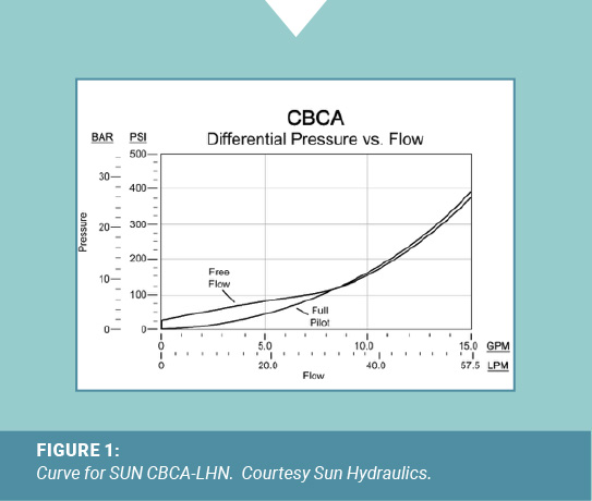
A counterbalance valve is a pressure control, not a speed control. The valve opens when the force balance on the valve exceeds the valve cracking setting, at which point the load starts to move. Depending on the load pressure and valve size it may take a very small valve opening for load to be moving at full speed. Consider the following pressure vs. flow curve for a 15 gpm rated, 3:1 pilot ratio counterbalance valve.
 CURVE FOR SUN CBCA-LHN. Courtesy Sun Hydraulics.
We can see that at rated flow, the resistance through the valve is 400 psi when piloted fully open. The valve could have a setting of say 3900 psi, but if release pressure is exceeded rapidly then the valve could be forced fully open. If the load pressure is higher than 400 psi then we do not want to pilot the valve fully open because we will have a runaway load. We would then lose pilot pressure, the valve will close, pressure in the fluid supplied to the actuator would build rapidly, and then the cycle may repeat. We would have valve instability (chatter). So the counterbalance valve is not a flow control, but the flow resistance through the valve is very important to stability. If the counterbalance valve is too large for the flow rate being supplied, it will operate very close to the cracking pressure position all the time and it may chatter.
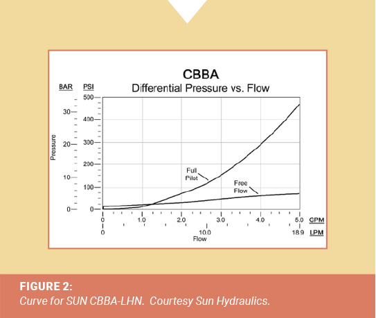
The following curve is for a much more restrictive counterbalance valve that is in the same cartridge cavity size. The free flow to raise resistance is still low, but the counterbalance poppet to seat flow resistance is much higher. When this valve is piloted fully open the flow resistance is above 400 psi at 5 gpm (the previous valve had 400 psi resistance at 15 gpm). The curve goes asymptotic after 5 gpm so for flows higher than 5 gpm resistance increases rapidly. Looking at it another way, if we could extrapolate this piloted fully open curve to a load of say 2500 psi, it could not runaway at a flow of higher than say 7-8 gpm due to the flow resistance through the valve. This valve should be much more stable at lower flow rates than the 15 gpm rate cartridge.
Curve for SUN CBBA-LHN. Courtesy Sun Hydraulics.
There are also different styles of counterbalance valves that function more like a pilot operated flow control and may not have a pressure setting. These valves allow you to select the control spool size for the desired flowrate and resistance.
So when specifying a counterbalance valve it is better to valve a smaller valve with high flow resistance. We want to err on the safe side and have a counterbalance valve that always restricts to control the runaway load. And of course we always want to size for the flow in that part of the circuit where the counterbalance valve is installed. So remember to factor in the cylinder area ratio to determine the actually exhaust from for the cylinder.
Now let’s look at pilot ratio.
 PILOT RATIO
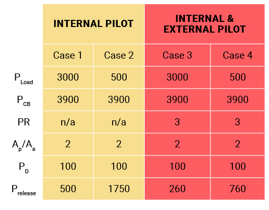
Pilot ratio will have a direct impact on stability because it is a key factor in determining release pressure. From the previous article, I used the following load cases (keep in mind that in all four cases the counterbalance spring setting is 3900 psi for a 3000 psi load):
One of the first things to remember here is that we could always use only an internally piloted counterbalance valve and this would provide the best stability. From Case 1 and 2 the release pressure stays fairly high and since the pressure required at the internal pilot to release is always holding the load back (preventing runaway), load/valve stability is much more likely. Unfortunately, circuit wise these valves would also be the least efficient option.
So an internally and externally piloted counterbalance is the choice for an efficient system. However, even though the valve is typically set 30% higher than the load pressure there are conditions where the external pilot pressure could potentially fully open the counterbalance valve and cause a runaway load, creating a load control stability is an issue. The situation where load stability can be the worst is when the load is heaviest. This is because when the load is high the external pilot pressure to release the valve is lower.
In Case 3 we can see that the release pressure to lower the load is only 260 psi, even though the valve is set at 3900 psi. Depending on how fast flow is introduced to the circuit (speed is ramped up) then it may be possible to overshoot this pressure and cause the counterbalance to open and the load runaway. This can happen if the load inertia is too high and pressure builds too quickly. When the load starts to runaway the external pilot pressure will drop, the counterbalance valve closes and then the cycle repeats. The biggest factor on whether this happens or not is the flow resistance through the counterbalance valve. With a more restrictive valve the chances of the load running away are less likely. Obviously this is a trade off with circuit efficiency, but the circuit must work smoothly.
It may be possible in this case to specify a valve with a lower pilot ratio to make the external pilot release pressure higher. If we specified a 1.5:1 ratio counterbalance of the same size valve as above, we get a release pressure at maximum load of 329 psi and 1043 at low load. This increase in valve stiffness may be enough to provide better load control stability.
SUMMARY
So even though the counterbalance valve is set 30% higher than the load, the pilot ratio and load condition can make it easy to release the valve. The flow resistance through the valve is a stabilizing factor that can help prevent runaway load and the corresponding valve chatter. So selecting a counterbalance valve is a balancing act (pardon the pun) between valve efficiency and load control, with the valve flow resistance and pilot ratio being the two main factors to be considered. High valve flow resistance and lower pilot ratio should provide more stability in most cases. Unfortunately, a bit of trial and error may still be required in some cases, but selecting these two parameters for higher flow resistance and higher release pressure should yield more stable load control results. λ
Share this information.
Related Posts


Sponsor

Sponsors