How to Keep Tabs on a Hydraulic Machine’s “Vital Signs”
By Brendan Casey, HydraulicSupermarket.com

My wife often asks me why I still do consulting work. She wonders why I happily leave the comfort of my office at times to crawl all over hydraulic equipment.
Well for one, I actually enjoy it. Two, it keeps me sharp. But perhaps most importantly, it keeps me in touch with the issues that hydraulic equipment users grapple with.
One of the things I’ve learned over the years is in the early stages of a consulting assignment, it’s better to ask good questions rather than dispense good advice.
A recent client had a series of catastrophic pump failures. These pumps were achieving less than half their expected service life. So naturally, they wanted some answers. At our first meeting, the client opened proceedings with a brief history on the machine, an account of the events leading up to the failures, and then pushed a stack of oil analysis reports across the table.
After I finished taking notes on what I’d just been told, I fired off my first question:
“What is the system’s normal operating temperature?”
Stunned silence. Client shrugs his shoulders.
“O-K … what’s the system’s usual operating pressure range?”
Blank look from client … “Err… dunno … we don’t monitor either of those things.”
At the end of the meeting we took a walk through to the control room. Both operating pressure and temperature were displayed on the default PLC screen – albeit along with a lot of obviously more important production information. Say no more.
But could YOU answer these two basic questions about the “vital signs” of the hydraulic equipment you maintain, repair, or support? If not, I strongly recommend you make the effort to get to know your hydraulic equipment better.
This information is easy to collect, can give valuable insight to the health of the machine, and is essential data if failure analysis is required. Here’s how I recommend you do it:
First you need an infrared thermometer, also called a heat gun. If you don’t have, you’ll need to invest around $100 to get one and then familiarize yourself on how to use it. Next, using a permanent marker or paint stick, draw a small target on the hydraulic tank below minimum oil level and away from the cooler return. Label it “1”. This marks the spot where you’ll take your tank oil-temperature readings.
By the way, the idea behind these “targets” is that regardless of who takes the temperature readings they’ll be taken from the same place each time.
If the system is a closed-circuit hydrostatic transmission, mark a convenient location on each leg of the transmission loop and number them “2” and “3.” Skip this step for open circuit hydraulic systems.
Next, mark a target on the heat exchanger inlet and outlet and number them “4” and “5” respectively. This records the temperature drop across the exchanger. The benefit of doing this is, if the oil flow rate through the exchanger and the temperature drop across it are known, the heat rejection of the exchanger can be calculated.
And if the system IS overheating, knowing the actual heat rejection of the exchanger can help determine whether the problem is the result of an increase in heat load—due to an increase in internal leakage, for example—or whether the problem lies in the cooling circuit itself.
For example, if a hydraulic system with an input power of 100 kilowatts is overheating, and the calculated heat rejection of the exchanger (based on the recorded temperature drop across it and design flow rate through it) is 30 kilowatts, then the efficiency of the system has fallen below 70%. And therefore, an increase in heat load is the likely cause. If on the other hand, the exchanger is only rejecting 10 kilowatts of heat, which in this example equates to 10% of input power, then it’s likely there’s a problem in the cooling circuit. Or there’s insufficient installed cooling capacity.
Next, if not already available, install a pressure gauge or transducer to record operating pressure, and if the system is a closed-circuit hydrostatic transmission, install a similar device to record charge pressure.
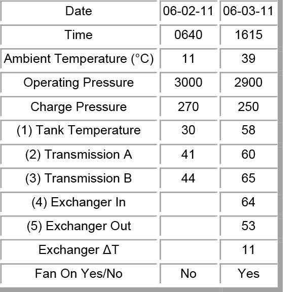
With that done, now draw up a table like the one below to record the date, time, ambient air temperature, operating oil temperatures, and operating pressure(s). Note that there is little point in recording the temperature drop across the heat exchanger if the fan or water pump isn’t running. And charge pressure is only relevant to closed-circuit hydrostatic transmissions (See Table).

In terms of compiling this data, it’s a good idea to take readings on the hottest and coldest days of the year and on a couple of average temperature days in between. This provides a baseline of information. Beyond that, taking readings at regular intervals—each day or shift for example, can provide early warning of impending problems. And if the system starts to give trouble, taking a set of readings will reveal if it’s operating outside its “normal” parameters.


