Keys to Success: 8 Building Blocks of Smart Fluid Power Systems

By Will Healy III, Regional Marketing Manager – Americas, Balluff Inc.
Manufacturers working to improve asset utilization and machine availability while simultaneously reducing unplanned downtime and nuisance stops are finding greater flexibility, efficiency, and visibility from incremental investments in smart fluid power components. To outmaneuver competitors, manufacturers are driving top performance from their equipment – no leaks, no sticking, no issues – and they know where the actuator is at every step of the automation process. Feedback and diagnostics are easily available, speeding up repairs and simplifying troubleshooting.
IO-Link, a well-established open (IEC 61131-9) communication technology, is empowering manufacturers around the globe with smart sensors, actuators, and devices from more than 300 component manufacturers. IO-Link devices not only provide automation process data but also report events and allow for auto-parameterization of devices on the plant floor, dramatically reducing the length of production stops. If you have an Industry 4.0 manufacturing initiative, IO-Link devices set a foundation for future smart factory projects throughout the plant.
Smart sensors and control components enable smart fluid power applications. When these technologies are combined with straightforward planning advice, manufacturers gain actionable insights through the implementation of key building blocks of a smart fluid power system.
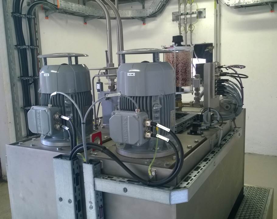
A smart hydraulic power unit.
Smart sensors
While this might be old news for some, many manufacturers are still learning how important closed loop control is for a fluid power actuator. Traditional sensing devices provide continuous or end-of-stroke feedback and fluid or process monitoring for better automation outcomes. Smart sensors take this to the next level through automatic configuration, detailed functional diagnostics, and application condition monitoring. Here are eight building blocks to better smart fluid power systems.
Building block 1: Pneumatic closed loop position feedback with smart sensors. The most common sensor used to create closed loop feedback in pneumatic grippers or cylinders is the magnetic field sensor, sometimes called a reed switch, a hall effect switch, or a magneto-resistive sensor. These devices provide end-of-stroke feedback for pneumatic cylinders, reporting either the extended or retracted position. Without this feedback, we assume the system works perfectly every time without leaks or sticking. But that risks collisions, damage, and downtime.
Continuous position feedback sensors are growing in use. These devices provide the linear position of the magnet on the piston, telling the controller the exact position of the end of the rod. Manufacturers use these sensors for error-
proofing, recipe adjustments, or even identifying the size of the part in a gripper. Traditionally integrated using analog signals, most continuous position feedback sensors are now being integrated using digital communication like IO-Link. These smart sensors can be configured based on a recipe or model change. They provide diagnostic information or multiple switch points beyond the discrete versions of the past. Factories currently benefiting from smart pneumatic systems have routinely started by implementing smart sensors on their pneumatic cylinders.
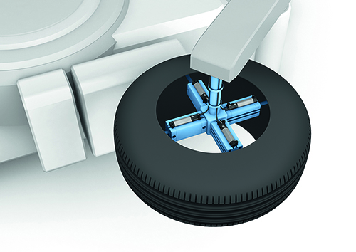
A robotic end effector for tire handling.
Building block 2: Closed loop hydraulic position feedback with smart sensors. Manufacturers with hydraulic systems commonly overlook closed loop position feedback. This is surprising due to the value those implementing sensors into cylinders, valves, and clamps realize. Cylinders with integrated sensors have been called smart cylinders for decades. Inductive sensors are mostly used for end-of-stroke position of hydraulic cylinders and valves. They typically detect the position of the cushions as the cylinder fully extends or retracts. When continuous position is needed for the hydraulic cylinder or valve, the cylinder is gun drilled, and the sensor is embedded into the cylinder, providing detailed feedback on the position of the piston.
Until recently, analog signals were the dominant form of connection, but now digital interfaces like SSI, industrial Ethernet, and IO-Link are beginning to dominate. These digital devices commonly report additional data beyond the position, like oil temperature in the cylinder, piston velocity/acceleration, and functional diagnostics. Parameters can be set digitally. With digital interfaces, hydraulic cylinders are now becoming the true “smart cylinders” and are one of the key building blocks when creating a smart hydraulics system.
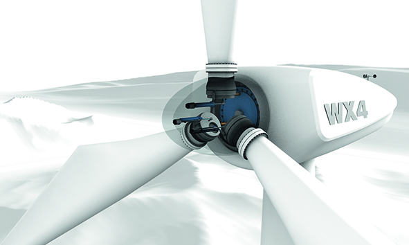
In this wind turbine rotor, hydraulic cylinders control the pitch of each blade individually.
Building block 3: Smart fluid/process sensing. A fluid power application is only as good as the power provided to it, whether it’s air or oil. The reliability of the pneumatic or hydraulic supply, therefore, is paramount to the success of the production or process. Sensing is an absolute requirement in this part of virtually every application, from pressure gauges on regulators to temperature and flow sensing on supply lines. But not all sensing is created equal. A visual dial is tough to read in the pit under a stamping press or up high on a piece of mobile equipment. Manufacturers are therefore implementing smart sensors with IO-Link for applications all over the power unit or shop air supply. These sensors not only provide measurement values, they can relay diagnostic tidbits like maximum pressure or the number of times power was cycled. Complex parameters can be stored in the controller or network interface; if a device fails, the parameters are sent automatically to the replacement device, dramatically shortening downtime and simplifying the skill required to replace the device. Smart sensor applications including level measurement, leak detection, pressure value, temperature measurement, flow measurement, valve position, and others abound in hydraulic power units.
Building block 4: Continuous condition monitoring for pumps, compressors and motors. A factory is only as strong as the weakest link. How many components and machines on the floor are past their service life? If we do not schedule maintenance for the machines, the machines will schedule maintenance for us. We must use limited maintenance resources in the most efficient ways possible. Unplanned breakdown of machines and components can botch a production run, cause equipment damage, or ruin a perfectly good afternoon. Often pumps, compressors, and motors are in hard-to-reach places like under equipment, a remote building, outside in the weather or, worst of all, in a locked room. You can monitor the condition of these devices periodically, but it seems like things always fail between cycles. With continuous vibration, temperature, pressure, and humidity monitoring, you can store data for pumps, compressors, and motor condition in a cloud or local central database. Later you can analyze the data for predictive maintenance trends or excessive vibration according to common ISO standards like ISO 10816-3. You can integrate condition monitoring into automation controllers or monitor it via a retrofit bolt-on black-box type system. Data can also be reported from the cloud to an app or website. The best part of this building block is the approachability for any size company; condition monitoring is as simple or as complex as skill allows.
Smart control components
Initially, IO-Link developments focused on sensor technologies. However, a recent explosion of control and output technologies has brought forward an opportunity for equipment builders and manufacturers to revolutionize how smart fluid power systems are built. It also creates deeper visibility into and greater efficiency of automated equipment. Fluid power systems are more empowered than ever before.
Building block 5: Pneumatic and vacuum smart systems control. In many automation applications, pneumatic valve manifolds provide a centralized control over pneumatic actuators. Commonly hardwired, they offer minimal information about the function and health of the device. With smart manifolds, however, we can now detect open coils, collect historical switching data, and receive potential diagnostic information to help with troubleshooting and maintenance. Devices like smart regulators bring a new level of application control into the smart pneumatic system by providing proportional pressure regulation, diagnostic information, and electronically adjustable setpoints. In addition, smart vacuum ejectors, generators, and manifolds provide valuable information about the lifting application, concerning, for example, a damaged suction cup or a new leak. Both devices can collect data about the application or allow real-time settings adjustments without resetting the whole system. The devices can report diagnostics for implementing predictive maintenance programs, such as cycle counts, acceleration, changes in measurement value over time, or even system temperature. Manufacturers who adapt industrial Ethernet or IO-Link pneumatic control devices as a building block gain more reliability and visibility in their systems.
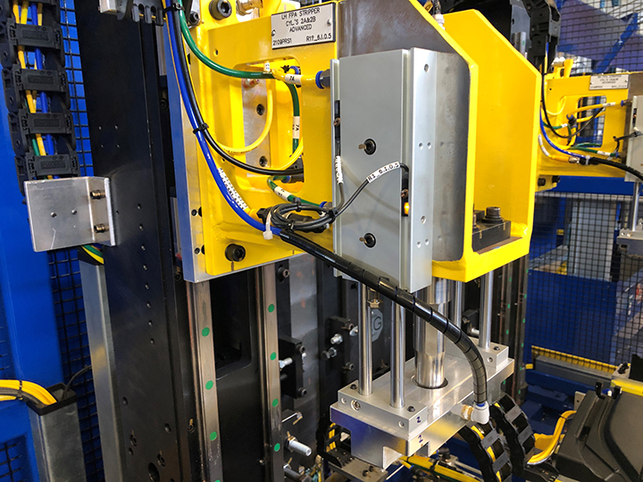
A pneumatic cylinder in a semi-automated assembly for an automotive tier supplier.
Building block 6: Hydraulic system control with smart valves and compact smart power packs. Leveraging smart proportional valves and smart directional control valves in hydraulic systems can result in the same value realized by pneumatic control devices. Smart proportional valves have built-in sensors and digital parameterization, eliminating the need for analog in the application, saving money and headaches for the installer and maintenance crews. Smart valves allow for pressure regulation, velocity control, and dynamic parameter configuration, increasing flexibility for process changes. Diagnostic data via IO-Link, including system temperature, operating hours, and other condition monitoring values, is also available. Smart power packs, built with either IO-Link devices or as one compact IO-Link device, provide detailed feedback on the heart of every hydraulic system. Compact smart power packs enable a high degree of automation and process stability with extensive diagnostics and self-test condition monitoring capabilities. When manufacturers combine this with closed loop hydraulic position feedback with smart sensors (described in building block 2), they produce a robust smart hydraulic system that provides users application flexibility, field-level visibility, and high efficiency.
Building block 7: Smart pumping and smart motor control systems. Digitalization and electrification of fluid power systems is real. Common pump failures like cavitation, liquid vaporization, dry running, heat buildup, or vibration should no longer be acceptable in the plant. The implementation of smart sensing technologies around the process of the pump is the low-hanging fruit, and it’s the starting place for many manufacturers to kick off smart factory initiatives. And with virtually any pump comes the motor, which should not be overlooked. Smart motor switch gear, contactors, overload relays, and starters provide integrated control of the motor circuit. For pumps requiring more precision control, smart inverter drives for the motor not only provide speed control, wear reduction, hammer reduction and variable pressure/flow/level control, they also bring parameterization, digital control, and diagnostics to the application. So by monitoring the pumping system’s inputs, outputs, and condition with smart sensors and smart control devices, dramatic decreases in nuisance failures are an easy win for any maintenance team. This is especially true when combined with predictive maintenance tools or a computerized maintenance management system.
Building block 8: Get started, now! Everything is just buzzwords and water-cooler chitchat until we act. The only way any of this creates value for manufacturers is to get started, and that’s something you can do today. Successful teams start with corporate goals and figure out how to tie their projects to one of those goals. They work their first projects with operational funds, and don’t immediately demand capital dollars. They are literate, learn from experience, and grow the scale of their projects over time. Each company is different based on what it can or can’t do, and that is okay.
When working to identify the first project, assess the following:
- What is causing the company pain right now?
- For which project can we get buy-in from the company?
- Which system if it failed would cause production problems immediately? What are the probable failure points? Which building blocks would help fix this problem?
- Who will own the project and take the leadership position? Others can help, but someone must own it.
- Is it necessary to involve IT? The answer to this should always be yes.
- Who else is on the team? Can the people in the room support the project in their daily decisions and actions?
So now you can get started! Identify two or three building blocks that have potential inside your organization. Identify the problems causing pain in your current fluid power systems. Identify that first project and the project owner, then build your project team. You can do this, just get started! λ
Share this information.
Related Posts

Eaton Acquisition Brings Industrial Hydraulics Market to Danfoss

Notable Words: Hydraulics & Electrification – The Future Is Bright

Danfoss Appoints President of Hydrostatics Division
Danfoss Hydraulic Pump Wins Award
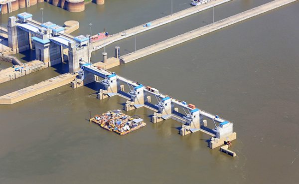
Civil Service: Modernizing the Hydraulics in Dams and Locks

Meet the Staff of the IFPS
Sponsor

Sponsors