Tank Optimization
An Underutilized Way to Improve Hydraulic Equipment Efficiency
By Jeremy Crookshanks, Group Product Manager, Hydraulic and Lube, Schroeder Industries.
In recent years, trends towards electrification, rising oil and fuel costs, and general concerns about sustainability have left engineers constantly striving for improved efficiency in hydraulic equipment designs. One aspect of hydraulic machinery ripe for optimization is the hydraulic tank.
Many machines operate with an excess of fluid in oversized or inefficiently designed reservoirs, adding dead weight to the machine, reducing efficiency, and increasing fluid recycling and replacement costs.
A myriad of benefits can be achieved through optimizing a machine’s hydraulic tank, including increased energy efficiency, weight savings, steel and oil savings per machine, CO2 emission reduction, roll off carbon footprint reduction, additional space for other features, and more.
What is Tank Optimization?
Tank Optimization is chiefly concerned with reducing the size and volume of the hydraulic reservoir. The two primary factors which determine the level of optimization possible are volume utilization and fluid velocity within the tank.
Volume Utilization
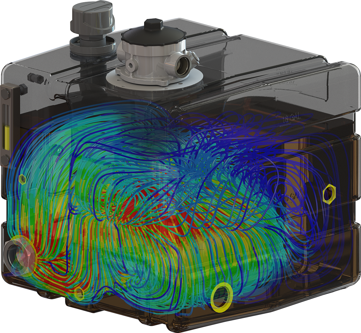
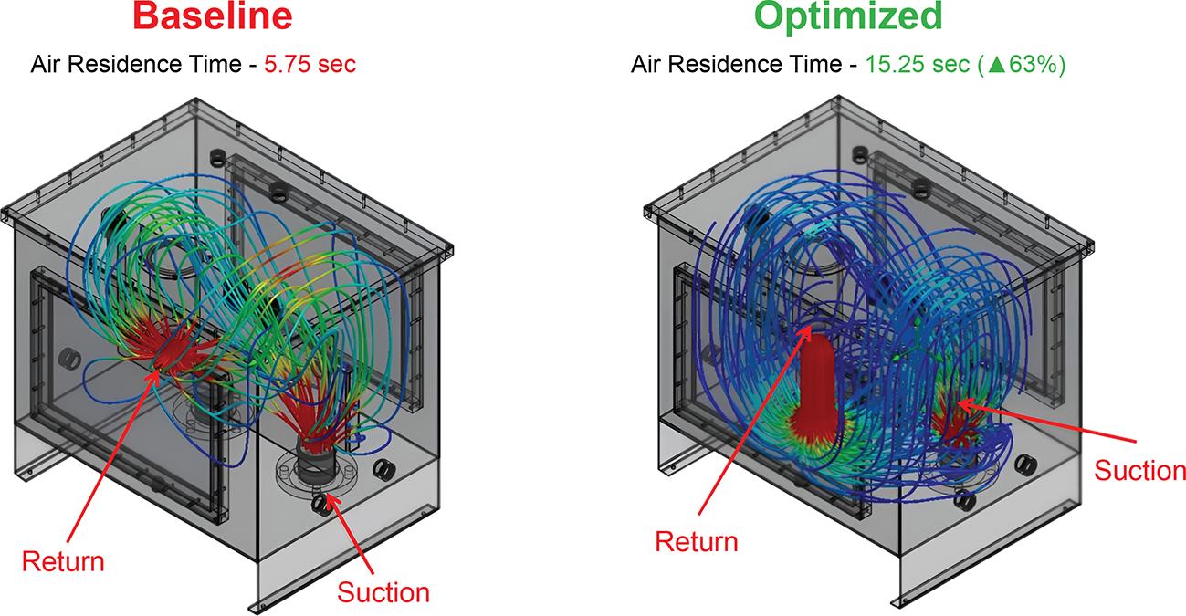
In an efficiently designed hydraulic tank, every cubic inch of the fluid volume should turn over within the reservoir. Digital simulations can be performed to determine if the reservoir is being utilized to its fullest. If there are “dead zones” in the tank where the fluid doesn’t circulate, then the fluid might as well not be there in the first place. Dead zones indicate the potential to downsize the tank and reduce the overall fluid volume of the hydraulic system.
Fluid Velocity
In addition to volume utilization, the fluid velocity—or the speed at which fluid moves into and through the reservoir—is another important factor in tank optimization. The fluid velocity dictates how adequately the tank can de-aerate and whether there will be splashing within the reservoir at the fluid surface.
Deaeration is of particular importance for hydraulic equipment, as air entering the hydraulic lines can cause a variety of problems, including:
- Gaseous cavitation. As air bubbles coalesce, grow, and collapse inside a hydraulic system, it causes loud noises and can potentially damage the internal hydraulic components.
- Spongy hydraulics. Unlike hydraulic fluid, air is compressible. As a result, too much air contamination can cause a delayed response, or ‘spongy’ feeling in a hydraulic system instead of an instant reaction. The result is inefficient, unpredictable, potentially dangerous system performance.
- Oxidation of hydraulic fluid. When oxygen reacts with hydraulic fluid, it produces varnish, a sludgy byproduct. This varnish increases fluid viscosity and can build up around valves, causing sluggish performance, damage to system components, blocked return lines and more.
To ensure optimal deaeration, the fluid velocity must be lowered as much as possible. This allows air bubbles to coalesce and dissipate at the surface of the oil and reduces splashing which can introduce more air into the hydraulic fluid.
Fluid velocity can be affected by altering the structure of the hydraulic tank itself, such as adding baffling geometry to disrupt and slow the fluid and reduce splashing. However, choosing the right in-tank return filter is also critical. Next generation in-tank filters which encourage reduced fluid velocity and air bubble coalescence for maximum deaeration have potentially the greatest impact on tank downsizing, even more so than the tank structure itself.
Limitations of Tank Optimization
Not every system is necessarily eligible for substantial reservoir downsizing through tank optimization. The chief limiting factor for tank optimization is the cylinder draw down volume of a given piece of machinery (i.e. the volume of fluid required to extend the hydraulic cylinders). The more cylinders there are, and the higher the draw down volume of the machine, the more fluid is required in the reservoir.
Still, tank performance can be enhanced by improving filtration and updating the geometry and baffling of the tank to increase efficiency and reduce dead zones, so revisiting the design of any given tank for potential improvement is still worthwhile.
The Benefits of Tank Optimization
With the fundamentals of tank optimization established, what benefits are there to OEMs and equipment users? Reducing the volume of a hydraulic tank comes with a variety of perks, chiefly: Improved energy efficiency, cost savings, increased machine space, and sustainability benefits.
Improved Energy Efficiency
Tank optimization allows for weight reduction by reducing the size of the tank and volume of hydraulic fluid within the system. Reducing the weight of a machine directly affects its energy efficiency, as a lighter machine requires less energy to move, and thus consumes less fuel. Additionally, with less hydraulic fluid circulating in the system, machine warmup time is reduced, allowing more energy to go towards actual operations.
This not only benefits diesel or other fuel-powered machinery but is critical for the viability of electric-powered machines. Since electric drive equipment relies on much more limited onboard battery power, any improvements to energy efficiency increase the operational time of the machine.
Cost Savings
A properly optimized tank saves money in several ways. First, hydraulic fluid must be replaced regularly. Recycling costs and new fluid purchases, account for a large portion of the expense over a machine’s lifetime. With less fluid to replace in an optimized reservoir, fluid replacement cost is reduced.
Second, with the benefits to energy efficiency already discussed, reduced energy consumption leads to reduced energy costs. Whether the equipment is powered by liquid fuel or electricity, ultimately, the cost of fuel is reduced.
Finally, with a smaller reservoir requiring less material to manufacture, some savings are immediately realized when the machine is first built.
Increased Machine Space
When a machine is being newly designed or updated, taking time to optimize the tank can free up onboard space for OEM engineers to further innovate and improve the equipment’s functionality and efficiency. This free space can accommodate larger batteries or fuel tanks, or potentially lead to a reduction in the overall size of the machine.
Sustainability Benefits
Sustainability is a growing concern across virtually every industry, and all the above benefits of tank optimization can have an additional impact on a machine’s relative eco-friendliness by reducing fuel and material consumption, as well as enabling electrification.
For a machine running on fossil fuels such as diesel or compressed natural gas, when less fuel is consumed, less carbon dioxide and other harmful emissions are produced. Any improvements to energy efficiency thus have a direct impact on emissions. Additionally, the carbon footprint of a machine’s initial construction is reduced when less materials are required to make the smaller hydraulic reservoir.
Furthermore, reducing the volume of hydraulic fluid needed to power a machine means less fluid must be replaced over time. This results in less hydraulic fluid being added to the waste stream, as well as reducing overall fluid demand and therefore mitigating the environmental impact associated with producing the hydraulic fluid in the first place.
Optimizing hydraulic tanks to the fullest extent can also open new possibilities for equipment electrification. Electric power is rapidly gaining ground as a sustainable alternative to fossil fuels, but electrification is hampered by the limitations of onboard batteries compared to liquid or gaseous fuels. Improving the energy efficiency of a machine through tank optimization increases the viability of electric power by reducing the amount of energy needed to power the machine. Additionally, space savings imparted by the reduction in reservoir size can allow for larger onboard batteries which further increase the operating time of the machine on a single charge.

Case Study: Tank Optimization in Practice
The benefits of tank optimization go beyond just theory. In one Schroeder Industries case study, a forestry OEM saw substantial savings when optimizing the hydraulic tanks on a series of stump grinders.
Through simulations of the OEM’s existing 75.7 liter (20 gallon) tanks and a TNK12 (45.4 liter/12 gallon tank) optimized for greater efficiency, it was discovered that the TNK12 would provide equivalent deaeration to the existing tanks with a 40% reduction in volume.
With 500 stump grinders being produced annually, saving 30.3 liters (8 gallons) of hydraulic oil per unit meant 15,141.7 liters (4,000 gallons) of oil saved overall. This translated into $28,000 in cost savings per year on oil alone. The oil savings were also imparted onto end users of the stump grinders via decreased cost of ownership associated with lower oil usage due to the optimized tank. Additional opportunities to improve the equipment design resulted from the reduced tank volume.
Downsizing the reservoir and reducing the amount of oil required also lessened the OEM’s annual carbon footprint. By reducing the oil usage of each stump grinder, the OEM’s annual carbon footprint reduction came to approximately 41,730.5 kg (92,000 lbs) of CO2 saved. In turn, the machine end user’s oil consumption will be reduced, further compounding the carbon reduction over the equipment’s lifetime.
Final Thoughts
For those machines whose hydraulic tanks can be significantly optimized, OEMs can expect to see reduced up-front costs for manufacturing through reductions in material and hydraulic fluid required. End users will also enjoy reduced hydraulic oil expenses and improved energy efficiency. And, ultimately, tank optimization improves the sustainability of the equipment through improved energy efficiency, reduced oil usage, and by opening doors for increased machine electrification.
As they further refine their equipment designs, OEMs across every industry should be asking themselves: Is my hydraulic tank optimized? If not, they and their customers could be missing out on considerable savings.

