Test Your Skills: Calculate the Oil Flow Rate & Pressure From a Pneumatic Intensifier
 Air-oil intensifiers combine advantages of both pneumatics and hydraulics in one system. Air is spongy and lacks precision and stiffness, while hydraulic oil is rigid and allows for precision metering to operate actuators. Air pressure is limited to about 1.03 MPa (150 psi), while commonly available hydraulic components can be operated at pressures to 20.7 MPa (3,000 psi) and above.
Air systems, consisting of a compressor and loop distribution system, exist in most shops. A number of air-oil systems are available as off-the-shelf units or are inexpensive to fabricate. Perhaps the simplest air-oil system is an automotive lift that applies air pressure from a tank, directly to a large diameter ram that lifts a pan hoist. Here air pressure acts directly on a ram large enough that 1.03 MPa (150 psi) against a 200 mm (approximately 8 in.) diameter ram will lift a theoretical weight of more than 3,400 kg (approximately 7,500 lb). This system is slow and cumbersome because air transfer takes time and a large storage tank is necessary for the fluid, compared to modern lift systems that use high pressure hydraulics and small power units.
More common are portable bench press units and hydraulic intensifiers that use a combination air-oil cylinder to multiply relatively low air pressure to a hydraulic pressure of 3,000 psig and higher. Because machinery is simplified, initial and operating costs are low compared to hydraulic units that would require a more expensive power pack (motor, pump, reservoir and valving), in addition to hydraulic hoses and plumbing.
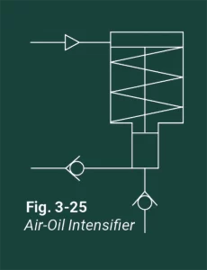
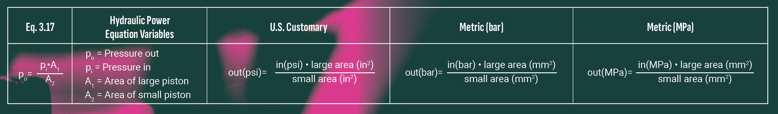
In a typical air-oil intensifier (Fig. 3-25), a large diameter air piston is connected rigidly to a small diameter oil piston. Using the concept of force multiplication, the small piston converts a relatively large force into a high pressure output but the volume is reduced by the factor of the force multiplication. The oil pressure available at the outlet of the intensifier is a function of the air pressure and ratio of the area of the large air piston to the area of the small oil piston. The balance of pressure and force for the intensifier is given by:
Since the pistons are connected together, the strokes of the air cylinder and oil cylinder are equal. Solving for air consumption to power an air-oil accumulator where air cylinder and intensifier cylinder bore diameters are given, and the oil flow rate is specified, is a five step process:
- Determine the pressure in the air cylinder to generate the required oil pressure in the intensifier. (Must determine the area ratio of the air piston to the hydraulic piston) (Eq. 3.17)
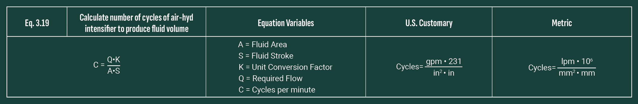
- Determine cylinder rod cycle rate to supply the specified lpm/gpm oil flow. Use Eq. 3.19.
- Solve for lpm (cfm) flow required for air cylinder bore, stroke and cycle rate. Use Eq. 3.8 from Outcome 3.14.
- Calculate the Compression Ratios. Use operating pressure at the cylinder.
- Convert lpm (cfm) to Nlpm (scfm) using Eq. 3.12.
Example:
Single acting, spring return air-oil intensifier with 10:1 ratio required to produce 7 MPa pressure at sea level of hydraulic pressure and output oil flow rate of 4 lpm. The intensifier has a 63 mm bore on the air side and the hydraulic side is a 20 mm bore with a stroke of 100 mm. What is the free air consumption to accomplish this?
Step 1 is to determine the air pressure required. Since the hydraulic pressure requirement is known and the area ratio is known, then use Eq. 3.17 to solve for the air pressure value, which is 0.7 MPa.
Step 2 is to determine the cycle rate necessary to produce a flow rate of 4 lpm using Eq. 3.19.
C=(Q•K)/(A•S)
Solving for the cycle rate yields a result of 127.32 cycles per min. to achieve the 4 lpm flow rate.
Step 3 using Eq. 3.8.
Q=(A•S•C)/K
The air consumption to accomplish the desired output is 39.69 lpm.
Step 4 is calculating the Compression Ratio using Eq. 1.1. The operating pressure is 0.7 MPa at sea level, so the Compression Ratio is:
(0.7 + 0.1)/0.1 = 8
Step 5 using Eq. 3.12
Qtot = (Qext + Qret) • CR
Nlpm = (39.69) • 8
Nlpm= 317.52
TEST YOUR SKILLS
1. An air-oil intensifier with a 4 inch diameter bore and 2 inch stroke powers an oil piston intensifier with a 0.5 inch diameter bore. What would be the maximum oil pressure from air supplied at 140 psig? (Refer to Fig. 3-26).
a. 1,120 psig.
b. 8,960 psig.
c. 9,900 psig.
d. 11,200 psig.
e. 18,860 psig.
2. A single acting piston (spring return) type air-oil intensifier with a 3 inch diameter bore and 1.5 inch stroke powers an oil piston intensifier with a 0.5 inch diameter bore. How many scfm of air would be required to deliver 1/4 gpm oil at a pressure of 4,000 psig? (Ignore the pressure required to compress the return spring.)
a. 8.56 scfm.
b. 10.31 scfm.
c. 18.22 scfm.
d. 20.63 scfm.
e. 24.65 scfm
See the Solutions
1-b and 2-b
Share this information.
Related Posts


Sponsor

Sponsors