Test Your Skills: Application of Proportional Valves
There are many applications for proportional solenoids in the control of hydraulic pressure and flow in both mobile and industrial applications.
The terms pressure differential and pressure drop indicate the same entity – a difference in pressure – and are often used interchangeably. In this discussion on proportional valves, we’ll use the term pressure differential. Proportional valves are typically catalog rated for a nominal flow at a 5 bar (72.5 psi)
pressure differential per flow path for a total 10 bar (145 psid), and a total loop differential across the valve equal to system pressure minus load and return line pressure or ΔpV = pS – pL – pT. In reality, however, very few systems have such an exact pressure differential. Therefore, it is necessary to determine the size of valve, based on the requirements of the system that it will be controlling. To maximize the performance
characteristics of a proportional valve, a more thorough examination must be conducted of not only the required actuator flow but also of the available pressure to drive flow through the valve.
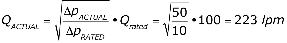
In most applications using industrial type proportional valves, flow is simultaneously metered in and out of the actuator (much like a pair of interconnected flow controls with sharp-edged orifices) in some proportion to the magnitude of the electric input signal, to provide precise control. And for a sharp-edged orifice of a given size, a mathematical relationship exists between the flow rate through and the pressure differential across the orifice such that:
Flow is proportional to the square root of the pressure differential and is expressed as:
![]()
Meaning, that if the pressure differential is increased by a factor of 4, the flow will double. For example, with a given size valve: If QRATED = 10 lpm at ΔpRATED = 10 bar, what is QACTUAL if ΔpACTUAL = 40 bar?

Where:
ΔpACTUAL is the actual (or required) pressure differential across the valve
ΔpRATED is the catalog rated pressure differential across the valve
QACTUAL is the actual (or required) flow passing through the valve
QRATED is the catalog rated flow through the valve at a given pressure differential
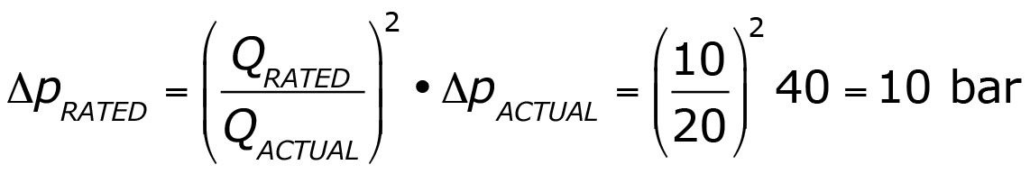
Conversely, pressure differential is proportional to the square of the flow and is expressed as: Δp::Q2
Meaning that, if the flow is reduced by half, the pressure differential is reduced to 1/4.
For example, with a given size valve: If ΔpACTUAL = 40 bar and QACTUAL =
20 lpm, what must ΔpRATED be if QRATED = 10 lpm?
Initially, increasing the pressure differential will increase the power available to the actuator and the higher flow will outweigh the power lost by the increased differential across the valve. Beyond a certain point, however, the power lost due to the increasing pressure differential becomes larger than the power gained by higher flow to the actuator, as shown in figure 1.
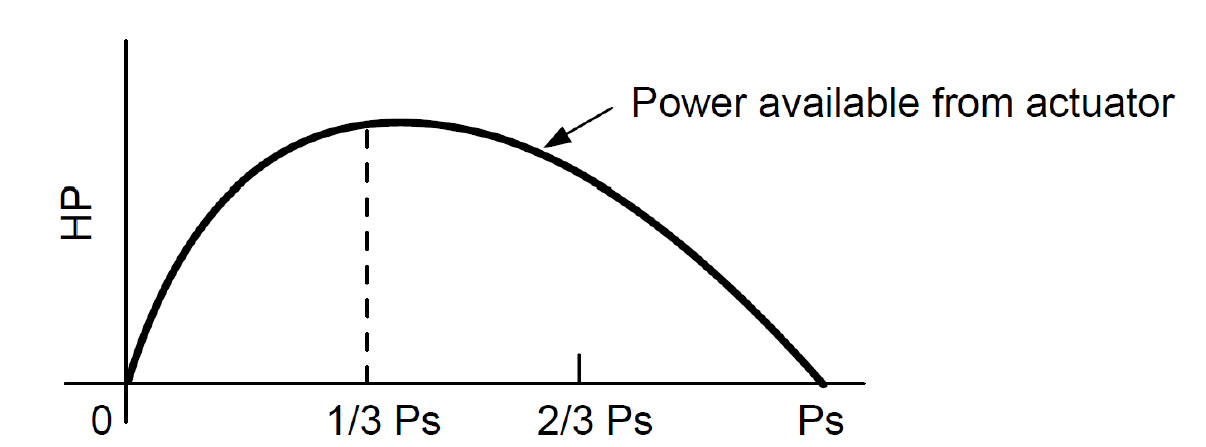
Figure 1: Pressure drop across valve (ΔPV ).
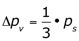
Experience has shown that this point occurs at approximately 1/3 of the maximum available system pressure and can be calculated as:
Where: ΔpV = Total valve pressure differential
pS = Available system pressure.
For example, if applying this to a system with a maximum system
pressure of 150 bar (2,175 psi), if the sum of the pressures acting on the load (including acceleration, friction, and pressure losses across other connected components and plumbing) and return line back-pressures add up to 100 bar (1,450 psi), 50 bar (725 psi) remains and is the differential that will drive flow across the valve. Assume that the system has a 200 lpm
(53 gpm) flow requirement.
The graph in figure 2 is for a valve that at 100% command, passes 220 lpm (58 gpm) at a 10 bar (145 psi) differential (flow curve 1). On the surface, this seems like a reasonable, energy-efficient choice because the valve can pass the required flow at a low-pressure differential. The reality is, however, the system has up to 50 bar (725 psi) available to drive flow and at 95% command, this valve can pass over 400 lpm (105 gpm) (flow curve 4), far in excess of the 200 lpm (53 gpm) required. To limit the flow this proportional valve can pass at a 50 bar (725 psi) differential, the spool command would have to be set to about 63% of its full stroke – effectively a 37% reduction in its available control range.
The graph in figure 3 is for a valve that at 100% command produces approximately 100 lpm (26 gpm) at a 10 bar (145 psi) differential (flow curve 1) which compared to the 220 lpm (58 gpm) valve is, on the surface, too small.
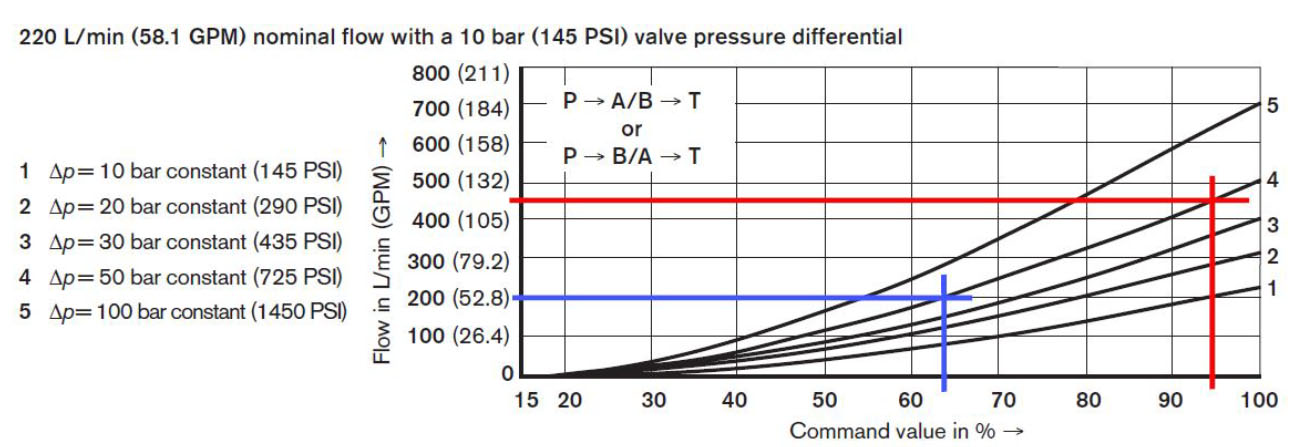
Figure 2: Nominal flow with a 10 bar differential (flow curve 1).
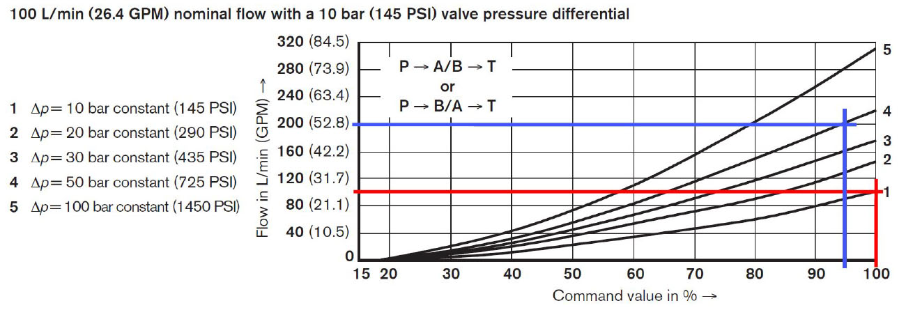
Figure 3: 100 lpm at a 10 bar differential (flow curve 1).
What if the valve was sized to take advantage of the full spool stroke at the available pressure differential of 50 bar (725 psi) to pass the required flow of 200 lpm (53 gpm)? Plugging in the known quantities into the equation for QACTUAL:
At 50 bar (725 psi) pressure differential, and a 95% commanded spool stroke, this valve passes about 200 lpm (53 gpm) (flow curve 4), equal to the system’s 200 lpm (53 gpm) requirement while providing some additional flow capacity.
The purpose of using electrohydraulic proportional valves is to provide control. A valve that is sized to provide the metering of flow across the full spool travel offers the best resolution and performance. It is well understood that a flow moving from a higher to a lower pressure zone without doing useful work is energy lost in the form of heat and the pressure losses incurred using a properly sized proportional valve is no exception. Simply increasing the size of the valve will not provide for a more energy efficient system because the valve must still be throttled to the equivalent cross sectional area to regulate flow, resulting in the same magnitude of pressure loss and heat generation. One way to make the system more energy efficient is to dramatically reduce the maximum supply pressure and substantially oversize the valve to pass the required flow at the lower available differential. However, larger proportional valves have bigger spools with more mass and are not as quick to respond to an input signal change as a smaller valve flowing at a higher pressure differential. Using the higher available pressure differential to drive the required flow through a smaller valve (while respecting the power limits mentioned earlier) certainly is less energy efficient, sometimes significantly so, but it is the price to be paid for greater control.
Proper sizing of industrial type, electrohydraulic proportional valves can be a rather involved, multistep process but is critical in performance-dependent systems.
Test Your Skills
1. When the inlet pressure to a proportional valve is doubled with no change to the outlet pressure, the resultant flow is:
a. reduced by 50%.
b. the same.
c. doubled.
d. increased by 141%.
e. increased by 400%.
2. Increasing the Δp through a valve beyond 1/3 of the available system pressure:
a. increases the power available to the actuator.
b. decreases the power available to the actuator.
c. causes the actuator to reverse.
d. has no effect on the system.
e. reduces the heat load in the system.
See the Solutions
1-d and 2-b.
Share this information.
Related Posts

No Pressure: Finding the Right Transducer for Your Hydraulic System

Patents Granted for Hydraulic Leak Containment Technology

Emerson Engineer Wins Powerwoman Award

Torque Division & Speed Synchronization Using 1:1 Counterbalances

Trelleborg Signs CRC as Distributor

NFPA Accepting Applications for Research Funds
Sponsor

Sponsors