The “STAMPED” Method

Designing & specifying tube assembly components
The acronym “STAMPED,” as used for hose assemblies, is equally as important to use when developing tube assemblies. The same factors apply; only the fabrication and installation will vary. Flow and pressure charts can be found from the same technical references.
Size: The size of the tubing is based on:
1. Flow (GPM)
2. Flow velocity (ft/sec)
3. Pressure
4. External corrosion
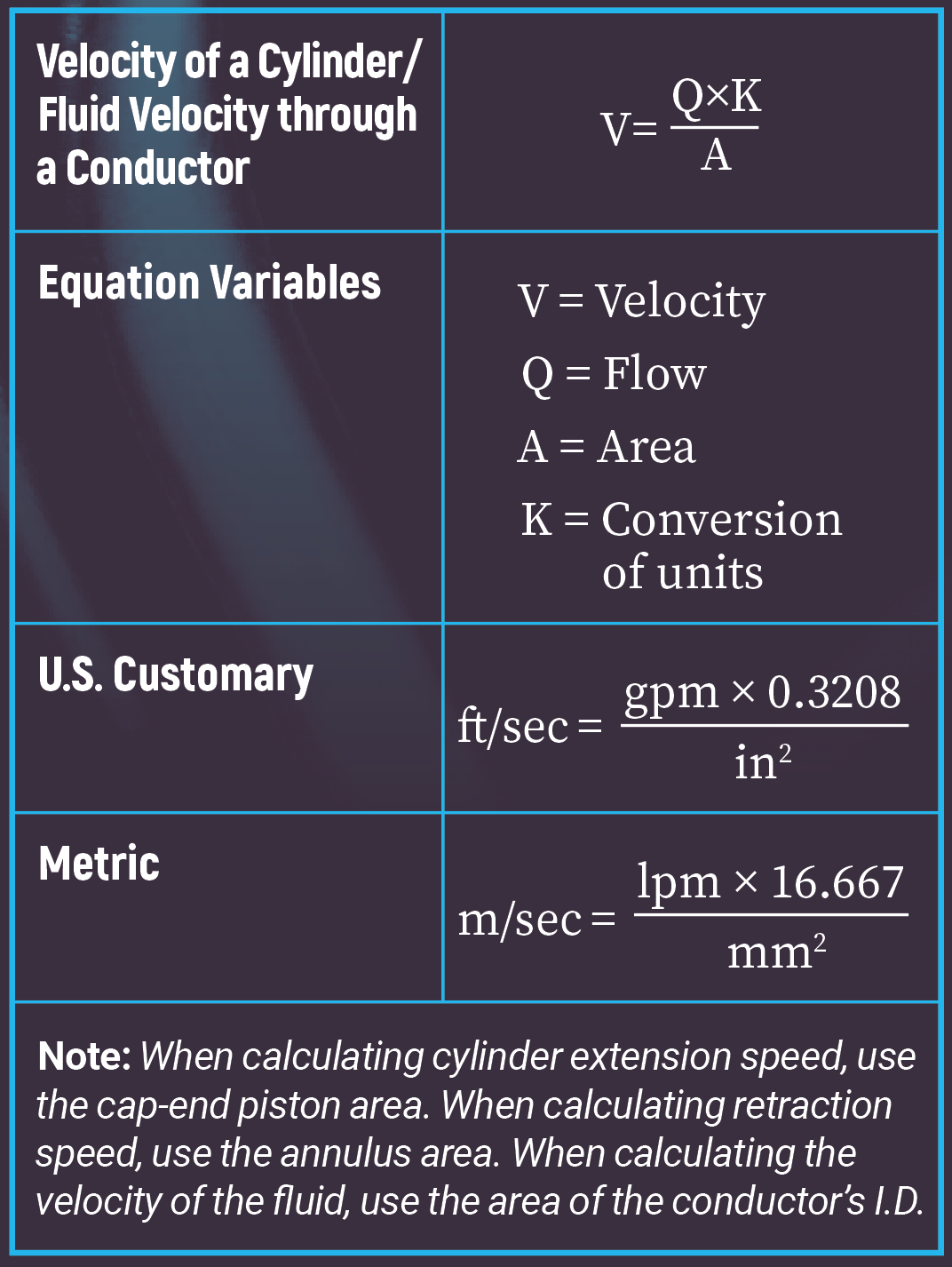
All hydraulic tubing is measured on the outside diameter (O.D.). The fluid velocity is based on the flow rate, liters per minute (lpm), or gallons per minute (GPM) flowing through the tube. This can be calculated or found on charts and in technical references.
Pressure is included in sizing here as well as under the “P” later on in “STAMPED”. Flow losses (pressure drop) can affect sizing the tubing. Length of line and configuration (elbows and number of fittings) can add to pressure losses, dictating a larger tube I.D. (see example chart at the end of this outcome). Low temperatures can also affect viscosity, which in turn will affect pressure drop. Wall thickness at bent tube sections will have reduced wall size. This will require the designer to determine the amount of reduction based on the bend radius and to recalculate allowable working pressure for the particular bend.
Temperature: The temperature can be a factor with tubing and fittings, but usually not until temperatures are extreme, above 175°C (350°F) or below 43°C (45°F). High and low temperatures can affect O-rings in fittings and the selection of tubing.
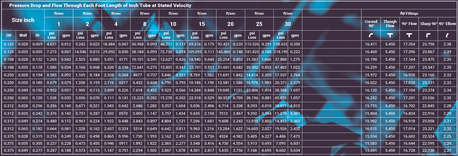
Hydaulic | Limited Detail SAE Size ∆P and Velocity Chart Combined
Note: The chart shown to the left is an excerpt from the IFPS Fluid Power Reference Handbook where you will find full versions of these (and many other) fluid power charts. Scan the QR code to view the product page for the Fluid Power Reference Handbook.
Application: The application will determine where the new or replacement tube assembly is to be used. Most often, only a duplicate of the original will be required, provided the original assembly gave acceptable service life. On some applications where corrosion is anticipated, the life of the system can be extended by increasing the wall thickness to compensate. To fulfill the requirements of the application, additional questions may need to be answered, such as:
Where will assembly be used, working and surge pressures, suction application, type of tubing, fitting type, fluid/ambient temperature, fluid compatibility, environmental, minimum bend radius, routing, government & industry standards, mechanical loads, excessive abrasion, expected service life, and external corrosion.
Material: The tube selection and fittings must assure compatibility with the fluid to be circulated in the system, as well as the environmental conditions.
Note: Many swivel elbow fittings contain O-rings which must be compatible with the fluid and environmental conditions.
Pressure: When selecting metal tube, it is vital to know the working pressure, including pressure spikes. Pressure spikes greater than the published working pressures will shorten the system service life and must be taken into consideration. Published tube working pressures must be equal to or greater than the system pressure. Thinning of the tube wall at bends must also be considered.
Burst pressures are reference pressures intended for destructive testing purposes and design safety factors only. Typically, for dynamic hydraulic applications, the minimum burst pressure rating is four times that of the maximum working pressure rating.
Ends: The ends identify the tube end fittings using manufacturers’ catalogs.
Delivery: Delivery is determined by availability, time to assemble, special packaging, shipping, and documentation.
Note: The table example chart shown above may be used for sizing fluid passages between hydraulic components when flow rates are known. Tabulations are based on a hydraulic oil having a viscosity of 155 SUS (CS 33.1) and a specific gravity of 1.
These pressure losses vary from the tables with changes in temperature, viscosity, I.D. roughness, and number of bends and fittings.
These notes and formulas apply to the pressure loss charts for SAE tubes and hose that follow:
- Flow is laminar if Nr < 2,000
- Flow is transitional if 2,000 < Nr < 4,000
- Flow is turbulent if Nr > 4,000
To correct the pressure drop values for specific gravity other than 1.0, multiply the pressure drop values by the new specific gravity. Corrections for viscosity change may be made directly to all laminar flow pressure drop values in the table by the ratio of New value (CS) ÷ 33.1 if the new value CS > 33.1. For new values below CS 33.1 the Reynolds number (Nr) may change to a value above 2000, in which case a complete new calculation should be made. This condition of Nr > 2,000 will most likely occur near the boundary (bold line) that divides transitional and laminar flow sections of this table.
TEST YOUR SKILLS
1. All hydraulic tubing is measured by its:
a. O.D.
b. I.D.
c. Wall thickness.
d. Material hardness.
e. Material type.
2. Anticipating a corrosion problem, one could:
a. Increase volume.
b. Decrease volume.
c. Increase pressure.
d. Decrease wall thickness.
e. Increase wall thickness.
See Solutions
1-a and 2-e.
Share this information.
Related Posts


Sponsor

Sponsors