The Vacuum Cup Explained
Understanding Vacuum Suction Cups in Material Handling Systems
By Daniel Pascoe, President, Davasol Inc.
This article is the opinion of the author, Daniel Pascoe, President of Davasol Inc., an industrial brand management firm. One of Davasol’s clients, Vacuforce LLC, based in Indianapolis, partnered with the author on this article. Contact Daniel Pascoe at dpascoe@davasol.com or Vacuforce staff via www.vacuforce.com
In any vacuum pick and place system, the most visually recognizable component is often the suction cup. While every part of a vacuum lifting system is vital, the choice of vacuum cup is particularly crucial. If the wrong type of vacuum cup is selected, it becomes immediately evident when the system struggles to lift and move the intended load.
With the vast array of vacuum cup options available, choosing the right one can be daunting, especially for those new to vacuum handling systems. Factors such as cup type, material, and manufacturer can all influence the application’s success. This article aims to de-mystify the selection process, helping you navigate the basic choices and avoid common misconceptions.
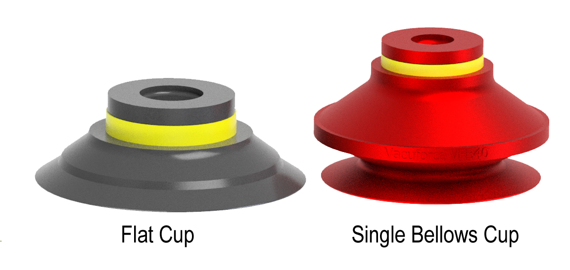
Figure 1
Types of Vacuum Suction Cups
Vacuum suction cups generally fall into two primary categories, flat and bellows, as shown in figure 1. While there are many variations within these categories, all vacuum cups are designed to securely grip and transport items using vacuum force. The decision to use one type over the other depends largely on the nature of the material being handled and how it needs to be moved once gripped by the cup.
Flat Vacuum Cups
Flat vacuum cups are ideal for situations requiring high stability, particularly in high-speed transfers, horizontal movements, or transitions through vertical/shear planes. They are also effective when the part needs to be rotated or turned. When vacuum is applied, the flat cup collapses, allowing the part to “locate” against the base of the cup. This base acts as a fixed reference point, providing exceptional stability. This feature is beneficial when handling heavy loads, thin materials, e.g. steel plates, or delicate items, e.g. wafers or freshly-molded plastics.
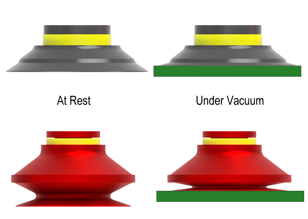
Figure 2
The stability of flat vacuum cups comes from how they spread the load across the entire diameter of the cup. As shown in figure 2, the height compensation or compression of a flat vacuum cup is minimal compared to a bellows cup. The workpiece, shown as a green rectangle in this illustration, is pulled higher when the cup is sealed against it and vacuum is applied. In figure 3, the difference between the datum surfaces of flat and bellows cups is illustrated, with flat cups providing flat contact cusps across its diameter, offering greater stability and reducing the risk of material distortion whereas the bellows cup offers contact only around it’s perimeter without a determined datum face to pull the workpiece against.
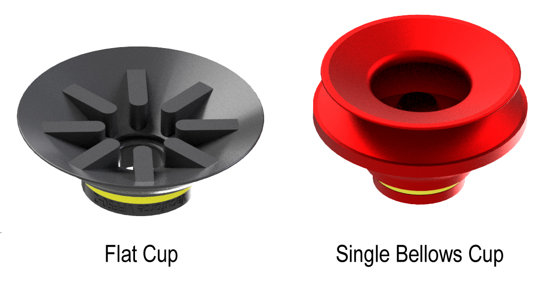
Figure 3
Bellows Vacuum Cups
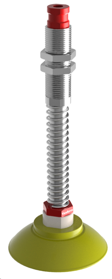
Figure 4
Bellows vacuum cups offer several advantages in specific applications. They provide flexibility in vertical positioning, particularly useful in tasks such as de-stacking sheets of paper or steel. Bellows cups can collapse onto the material before the vacuum is applied, unlike flat cups, which require precise positioning to ensure a proper seal. While flat cups can achieve vertical compliance using a sprung level compensator, as shown in figure 4, this adds complexity and cost to the system.
Another benefit of bellows cups is their ability to accommodate angled surfaces. If the material being handled is not perfectly aligned with the vacuum cup, a bellows cup can adapt to the angle, whereas a flat cup would require an articulated joint to achieve the same result.
Bellows cups are also advantageous in sheet separation tasks. When de-stacking thin sheets with flat cups, there’s a risk of picking up multiple sheets due to the vacuum’s perpendicular pull on the stack. Bellows cups, however, create a “peel effect” as they collapse, lifting the material slightly and independently of the machine’s movement, which helps to separate the sheets effectively. This would be particularly effective in a zoned circuit where the left side starts lifting before the right-hand side, for example.
Bellows vs. Flat Vacuum Cups:
A Detailed Comparison
Bellows vacuum cups offer a clear advantage over flat cups when handling products that are circular, convex, or concave. A bellows cup can conform to the shape of the object being lifted, whereas a flat cup lacks the flexibility to adapt to such profiles. Despite the multiple advantages of bellows cups, there are several factors where flat cups may be more suitable.
Flat vacuum cups are generally more cost-effective and provide superior stability, which allows them to operate at higher speeds. Additionally, the internal volume of a flat cup is smaller, meaning it takes less time to generate a vacuum. The reduced movement in flat cups when under vacuum also contributes to their longevity, as there are fewer stress points that could lead to cup material fractures.
Lifting Capacities of Vacuum Cups
The lifting capacity of a vacuum cup depends on two key factors: the sealing area of the cup and the pressure differential, or vacuum level, inside the cup. Vacuum is essentially the reduction of atmospheric pressure, which is typically 14.7 psi (29.92” Hg), within a confined space like a vacuum cup sealed against a load.
For example, if a vacuum cup has a diameter of 4 inches and the vacuum level is at 15” Hg, resulting in a 7.35 psi pressure differential, the lifting capacity can be calculated as follows:
Vacuum Cup Area: π r2, (Pi × radius of cup diameter squared) which equates to 3.142 × (2 × 2) = 12.568 in2
Pressure Differential: 7.35 psi
Thus, the vacuum “pressure” is 7.357 psi, therefore 7.35 × 12.568 = 92.37 pounds of lifting force.
If the vacuum level is increased to 24” Hg (with an 11.76 psi pressure differential), the lifting capacity rises to 147.8 pounds. The relationship between differential pressure and lifting capacity is linear.
It’s important to note that the volume, shape, or height of the vacuum cup has no impact on its lifting force. The lifting force is determined solely by the area of the vacuum cup’s sealing lip multiplied by the pressure differential.
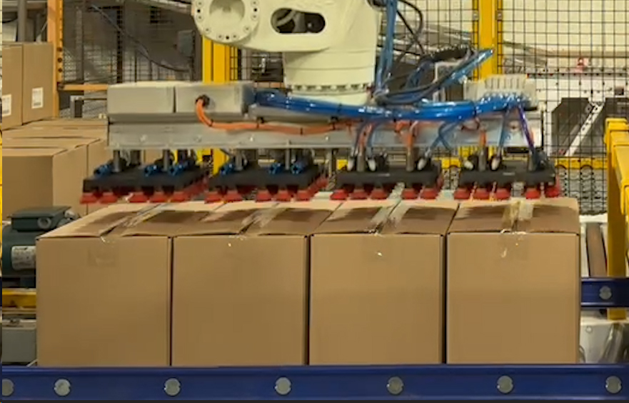
Figure 5
The calculations presented are theoretical but reliable, with safety factors being crucial for practical use. Often, the number of vacuum cups required is driven more by the need for stability than by lifting capacity alone. For instance, consider a standard carton measuring 12 × 18 inches and weighing approximately 40 pounds. A single 2-inch vacuum cup at full vacuum can lift nearly 50 pounds, meaning that six suction cups could lift 300 pounds. This provides a solid safety margin and ensures stability, provided the carton has adequate structural integrity. If the carton’s weight necessitates placing cups along the taped flaps to prevent structural deformation and add stability during transit, the safety factor increases. In figure 5 a scenario where lower-quality cartons is illustrated, requiring multiple rows of suction cups on the vacuum gripper to maintain stability and minimize flap deformation.
Vacuum Cup Materials
There are various vacuum cup materials available, with the choice typically based on one or more of the following characteristics:
- Vacuum Cup Hardness: The hardness, or durometer, of a vacuum cup is chosen based on its ability to conform to the surface of the product being handled. Softer durometers are ideal for materials such as cardboard, corrugated paper, or textured surfaces, as they enable the cup to create a reliable seal. For instance, a Shore hardness or duromater of 40, often found in natural or silicone rubber, is considered soft and suitable for these applications. In contrast, a nitrile or NBR compound typically has a Shore hardness of around 60, providing a firmer option for other types of materials.
- Heat Resistance: For high-temperature applications, such as handling injection-molded parts, silicone is typically used due to its ability to withstand temperatures up to 400°F. However, silicone should not be used on surfaces that will be painted or surface-treated, as it can etch into the material and prevent proper coating adhesion. This is also important if you are handling glass or decorative stone such as granite countertop handling. In such cases, alternatives like Viton may be preferable as it offers heat resistance up to 700°F, though it is harder with a durometer of around 60.
- Chemical Resistance: When handling corrosive materials, silicone is often the go-to choice. Natural rubber, while excellent for wear resistance in applications like handling cardboard or stone, performs poorly in chemically aggressive environments such as those involving oil, e.g. steel stamping. Nitrile rubber and polyurethane are often chosen for oil-rich environments due to better wear resistance and lower cost when compared to silicone.
- FDA-Compliant Silicone: When suction cups are used in applications involving direct contact with food or pharmaceuticals, they should be manufactured using FDA-compliant materials, such as silicone rubber. FDA-compliant silicone, as defined under FDA regulation 21 CFR 177.2600, meets stringent regulatory standards for safety and purity while providing excellent resistance to a range of temperatures. This ensures consistent performance in both hot and cold environments.
Most vacuum cup manufacturers provide comparison tables that detail the compatibility, hardness, and other characteristics of their available compounds. In addition to standard materials, there are specialized compounds like conductive silicone for handling sensitive electronics or modified Nitrile for resisting chlorine in metal stamping oils. Non-marking compounds are also available for applications like glass production.
For a starting point in vacuum cup selection, a single bellows nitrile cup is generally recommended. It is cost-effective and suitable for a wide range of applications. Depending on the specific requirements, this initial choice can be adjusted accordingly.


