Shifting Gears: Converting to an Electrohydrostatic Transmission
By Philippe Tottoli, E-mobility Program Marketing Manager, Poclain
Low- and zero-emission vehicles are making their way from the roads to the off-highway market driven by regulations and national environmental policies. Hybrid and electric machinery have merged onto both jobsite and field. This pressure has many mobile machinery OEMs looking for ways to electrify their traditional internal-combustion engine (ICE) models.
OEMs are faced with a number of challenges. For the end user, electrified machine performance must be identical to the equivalent ICE machine to carry out the same work. Likewise, the electric machine must offer acceptable range and battery lifetime to reach sufficient daily availability for work. The noise level of the electric machine must be significantly lower than the equivalent ICE machine to improve working conditions for the driver and reduce noise pollution in urban environments. Above all, to make economic sense, the electric machine needs to deliver a return on investment comparable to the equivalent ICE machine within a reasonable time frame. Lower operation and maintenance costs help the owner achieve the desired lower total cost of ownership.
OEMs are caught between the pressure to design to meet new regulations and increasing demand from end users facing tighter-than-ever schedules and changing rules.
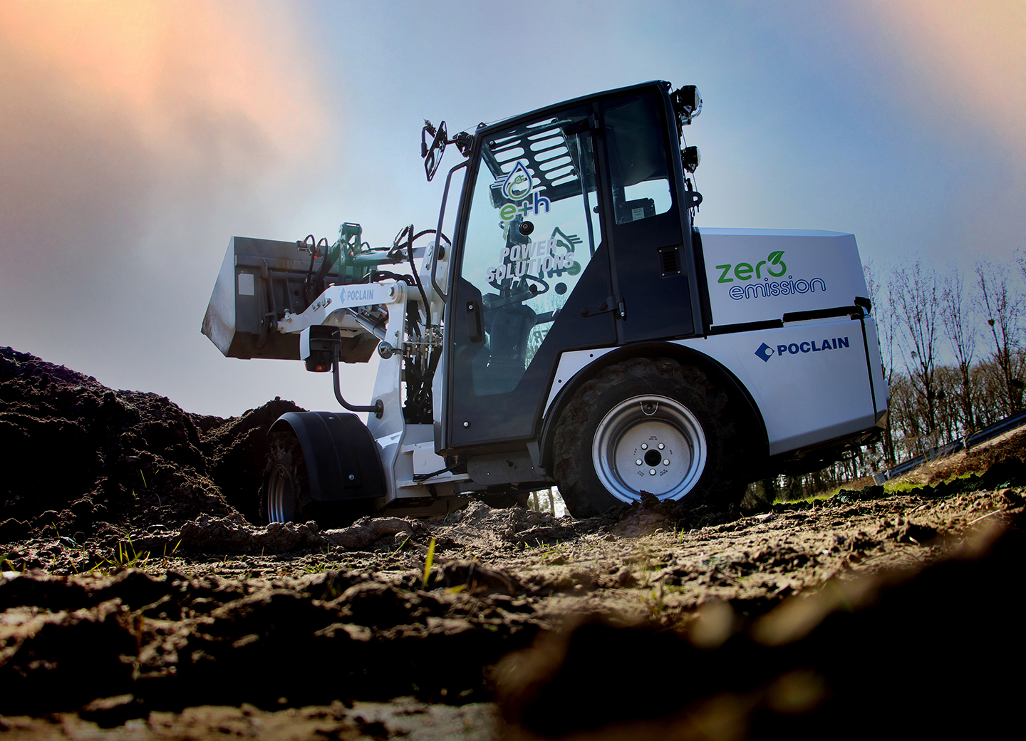
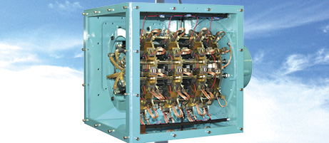
![]() For off-highway machine manufacturers caught in this situation, electrohydrostatic technology may be an answer because it does not require a complete machine redesign and allows for a high degree of commonality between the ICE and electrohydrostatic versions. Part and design commonality makes the transition easier for the OEM in terms of production changes, after-sales support, maintenance, as well as end-user training and adoption. By electrifying the hydrostatic system, OEMs are able to deliver the same benefits of time-tested, reliable cam-lobe hydrostatic technology without the emissions.
For off-highway machine manufacturers caught in this situation, electrohydrostatic technology may be an answer because it does not require a complete machine redesign and allows for a high degree of commonality between the ICE and electrohydrostatic versions. Part and design commonality makes the transition easier for the OEM in terms of production changes, after-sales support, maintenance, as well as end-user training and adoption. By electrifying the hydrostatic system, OEMs are able to deliver the same benefits of time-tested, reliable cam-lobe hydrostatic technology without the emissions.
An electrohydrostatic transmission is a system made of hydraulic, electric, power electronics, and electronic components combined with control software. The hydraulic components are typically hydraulic motors, drive pumps, and valves. The electric components are electric motors and batteries, which can include different technologies. The power electronics components are DC/AC inverters, an onboard charger, and a DC/DC converter. The electronic components include the electronic control unit, sensors, display, connectors, and accessories.
Electrifying an off-road mobile machine with an electrohydrostatic transmission can be broken down into a few steps: machine inspection, input data collection, transmission presizing, realization and optimization, and field monitoring. To illustrate the process, take the example of a mini wheel loader recently electrified by Poclain Hydraulics’ electromobility team. The mini loader, with an operational weight of around 1.8 tons, was originally equipped with a diesel engine and a hydrostatic transmission based on wheel-motors, hydraulic boom, and tools.
Machine inspection
The first step the team took after receiving the mini wheel loader and before starting any electrification activity was to perform a complete machine inspection and verify proper function. Once this was completed, the machine underwent a full battery of performance tests, including an inventory, to characterize all the hydraulic systems in their original configuration. The objective was to build a machine model for system simulation software to simulate the operation of the hydraulic systems. The team also carried out acoustic tests in the original configuration to measure the difference in sound level between the diesel and electrified machines.
Input data collection
The next phase was to gather the input data needed to design the transmission: machine duty cycle, machine mission profile, and geometrical and weight constraints. This phase of data collection and analysis was part of a connected engineering campaign.
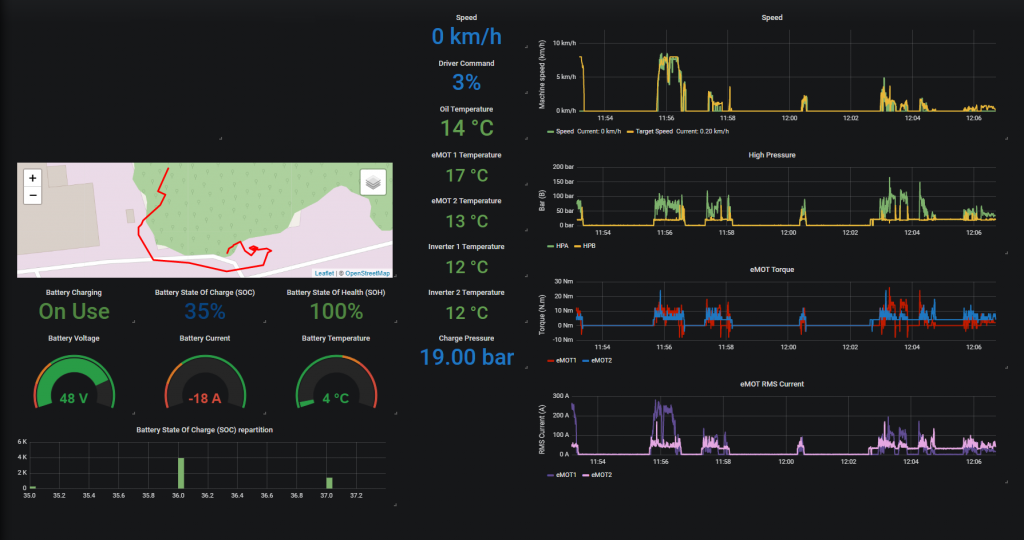
Confirmation of real-life duty cycles. The team sent the mini wheel loader equipped with a connectivity box into the field to perform a series of operations matching typical machine usage. The connectivity box was connected to the machine’s CAN bus to upload the data directly to the cloud. The team put the machine through a number of work scenarios to attain a large enough data sample. Work included traveling at different speeds, empty and loaded, on flat surfaces as well as uphill and downhill; moving the bucket up and down, and filling and emptying the bucket, among other operations.
Throughout these operations, the objective of the data collection was to confirm the machine’s duty cycle for the transmission and auxiliary functions. Obtaining in-depth knowledge of the duty cycle is a key step in the electrification process and has a major impact on the correct sizing of transmission components and power distribution to auxiliaries.
Defining the mission profile. Machine mission profile definition has a major impact on the required amount of energy embedded in the batteries and its distribution between transmission and tools.
For the electrification of the mini wheel loader, the team targeted a machine range of a complete working day with charging in the middle of the day. In typical use, the machine works intermittently during the day. To obtain the most realistic mission profile possible, the profile integrated operations with several of the most frequently used tools.
Geometrical and weight constraints. After validating the duty cycle and defining the mission profile, the team needed to characterize the machine geometry, weight distribution, and center of gravity.
Transmission presizing
After gathering the input data, the next phase was presizing the transmission.
Performance envelope. The first stage involved characterizing the performance envelope of the machine in the four quadrants. The performance envelope is given by the curve of the machine tractive effort as a function of the machine speed. From this curve, the performance envelope of the different components of the transmission were determined. This is actually the process of presizing the transmission components.
Define and simulate architecture. The team designed several possible system architectures to respond to the transmission requirements and the power distribution to auxiliaries. These architectures included the main hydraulics, and electric and power electronics components.
The team performed simulations for each of the defined architectures to verify whether their performance matched the requirements of the transmission and the power distribution to auxiliaries. Simulation is a very powerful tool that makes it possible to verify the overall performance of a system quickly to prevalidate an architecture without having to carry out tests on a real machine.
Select and presize electric and hydraulic components. Once the team defined the system architectures, it was time to drill down to the component level. Based on the input data and simulation results, they selected and presized the different components of the architectures. Components included a drive pump, closed loop circuit valves, hydraulic motors, inverters,
e-motors, a DC/DC converter, an onboard charger, an electronic control unit, a display, sensors, and connectors. At this point in the process, adjustments or component changes are still possible.
Selecting a final architecture by simulation. Among the simulations of the different system architectures, the team selected the one that best matched the system requirements based on the energy efficiency criteria, compatibility with economic constraints, and available space.
Realization and optimization
 After presizing the components, the next phase was practical realization, including transmission optimization and auxiliary power distribution.
Integration study. Once the architecture was defined and the dimensions of every component were known, it was possible to proceed with a detailed integration study of the system within the machine. In the case of the mini wheel loader, once the diesel engine, the fuel tank, the radiator, cabling, and several other components were removed, the team defined the available space for the electrohydrostatic drivetrain using the existing machine geometry.
When needed, they used a 3D scanner to digitize the machine geometry and environment. Then they defined the arrangement of the components to keep the weight distribution and center of gravity within the limits of the machine’s operational weight.
Control strategies and functional safety analysis. Based on the customer and machine requirements, the team specifies system and control strategies for all machine life cases. In this case, they performed a safety analysis to ensure the safety functions of the system based on generic customer and machine requirements. Then they programmed the software of the electrohydrostatic transmission before uploading it in the transmission electronic control unit.
Integrating the transmission. Next, the team mounted and assembled the electrohydraulic system into the mini wheel loader. Then they uploaded the vehicle control and e-hydrostatic transmission-embedded software into the electronic control unit.
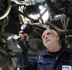
Machine commissioning. The last stage of electrification was the commissioning of the mini wheel loader. During this stage, the team checked, inspected, and tested every major component of the transmission and the power distribution to the auxiliaries at the individual component level and the integrated function level. The final result was a perfectly functioning and safe zero-emission electrohydraulic machine.
Field monitoring
Generally, the machine is fitted with a log box connected to the CAN bus that collects machine performance data and use. This is a powerful way to monitor performance under real customer operating conditions. We can also refine duty cycle and mission profile characterization to improve machine design and optimize transmission sizing for the next machine release.
Share this information.
Related Posts

Keys to Success: 8 Building Blocks of Smart Fluid Power Systems
How to Ensure Bolted Joint Integrity When Using a Compression Limiter in a Plastic Assembly
Universal Vacuum Grippers and End of Arm Tools

Is It Time to Rethink Open Loop Hydraulics in Agriculture Machines?

Hydraulic Hose Assembly Application Guidelines – ISO/TS 17165-2
Improving Wind Turbine Reliability
Sponsor

Sponsors