Top 5 Must Have Hydraulic Pressure Gauge Features
By Eric Deoliveira, Product Marketing Leader, Ashcroft, Inc.
If you work with any of the critical mechanical applications found in the modern world it is likely you also manage hydraulic systems. Arguably, hydraulic machinery far exceeds most other forms of mechanical power transmission. Excavators, tree harvesters, mining and tow trucks, and other hydraulic vehicles perform the harshest tasks on uneven terrains with heavy loads that apply tremendous forces on hydraulic systems.
Because each of these systems uses liquids in various forms to transmit power, you know that the inherent pressure feature of hydraulics must be managed properly. In the best-case scenario, a lack of sufficient pressure-level management in a system could lead to inferior output. In the worst cases, it could cause damage to equipment or physical harm to system operators.
Hydraulic pressure gauges play a critical role in regulating pressure by monitoring levels in either a specified part or the entire system to ensure things are operating normally. So how do you know which pressure gauge will work best in your hydraulic system? Just know what you’re looking for and choose carefully. As a pressure gauge product lead at Ashcroft – a recognized authority in temperature and pressure solutions —I have seen many scenarios where the wrong pressure gauges were selected and the impact that decision had on operations.
In this article, you will learn about the top five factors to consider when selecting a pressure gauge for hydraulic applications so you can be confident about selecting the best option to meet your specific needs. Let’s get started.
1. Resistance to Pressure Spikes
There are many situations where you may be relying on hydraulics in unpredictable conditions such as in a construction loader hauling materials over uneven surfaces. In these applications, an unexpected shock or force could quickly send pressure levels up by tens of thousands of psi. A malfunction or temporary slip in any part of a system could also cause a huge pressure spike.
Pneumatic systems can sometimes cushion a shock load because of its compressibility, while the much stiffer hydraulic system responds with a spike in pressure. If your pressure gauges aren’t adequately designed to manage these pressure spikes, it can lead to serious challenges with both efficiency and accuracy.
 As you compare options for pressure gauges, consider the maximum capacity of each option to determine whether or not it aligns with your requirements.
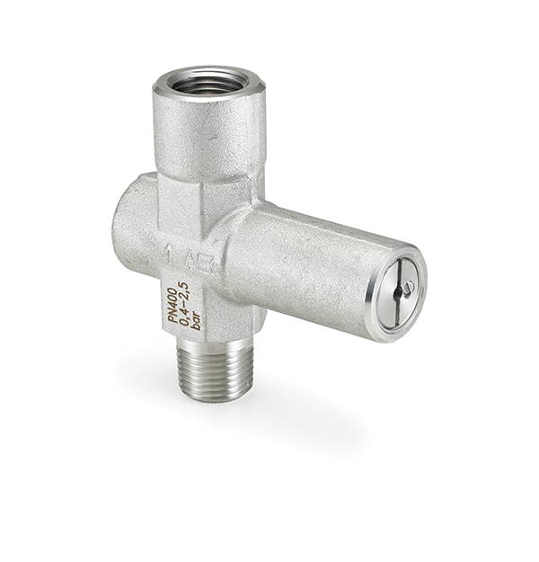
One accessory that can help with this issue is a pressure-limiting valve. These devices are designed to limit pressure up to a set value to prevent sudden pressure increases from damaging your gauge. Once the pressure drops below the specified value, the valve will reopen.
2. Ability to Withstand Extreme Temperatures
Hydraulic systems are often used in environments with extreme or unpredictable temperatures. Think about offshore mining equipment operated near the floor of the ocean, or construction vehicles working in places with sub-zero weather conditions. In these cases, there is a large difference in temperature between the hydraulic fluid and the working environment.
Because of the way temperature and pressure interact, temperature changes can cause corresponding shifts in pressure levels.
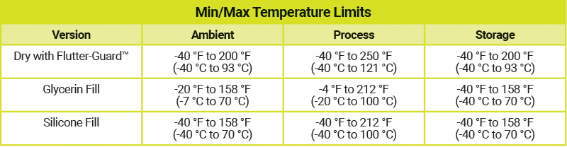
When comparing pressure gauges, make sure to check the device’s reference temperature for span calibration and the specific amount of offset to expect for a particular range. Also, consider a dry gauge ambient temperature and temperature of the fluid under pressure:
3. Protection from Vibration, Pulsation and Flutter
Vibration refers to the periodic or random mechanical oscillation caused by various components like motors, pumps, actuators, and hydraulic lines. This vibration can lead to flow disturbances or ripples, creating harmonic pressure waves that impact pressure instrument performance and longevity if not properly managed.
“Pointer flutter” occurs when consistent vibration or pulsation causes the indicator on a gauge to move very quickly back and forth between a small range on the dial. This in turn makes the gauge more difficult for an operator to read and interpret. There are many reasons why a hydraulic system might be emitting vibration or pulsations.
Some degree of flutter isn’t necessarily a sign that a system is failing or malfunctioning. As a rule of thumb, if flutter is causing your gauge’s pointer to move more than 5% across the full range of the device, you need to take steps to address whatever is causing the external vibration or the application.
Here are a few options to consider:
- Gauge dampening techniques like liquid fill, FlutterGuard or PLUS! Performance. These options help minimize movement of the gauge’s components to reduce or eliminate flutter issues, which reduces potential damage to the gauge and expands its life span. This solution also improves gauge accuracy and helps improve readability.
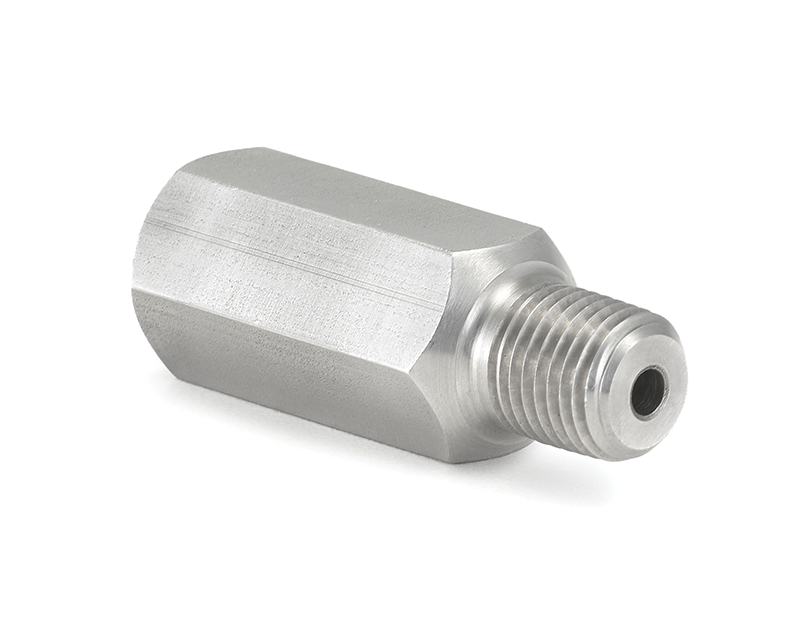 A pulsation dampener can also help with flutter. This is a piston-style dampener that uses an adjustable pin to restrict pulsation. The pin can be placed in one of several different-sized pinholes, allowing you to vary the dampening amount to suit your application requirements.
4. Quality Assembly and Composition
The material a pressure gauge is built from is a key factor in compatibility with hydraulic systems. Better quality materials mean a pressure sensor has a better chance of withstanding internal and external challenges. Remember, even an ordinary-sized pressure gauge for use in a hydraulic system is typically built from many different parts, including:
- The external casing that houses the entire unit and helps protect it from physical damage that affects operation. This is sometimes called the housing or enclosure. Stainless steel is the ideal option for a casing material. It is tough enough to withstand physical shock and can usually stand up to corrosive factors including moisture and extreme temperatures.
- Sealing components like gaskets and O-rings that are used to connect various parts while maintaining an airtight seal, are critical for accurate pressure readings. Be sure the sealing components are also made of a durable enough material to work in your system and operating conditions.
- Solid or open-front construction is another important assembly factor to consider. When a pressure gauge is pushed beyond its capacity, it may physically rupture. A solid-front gauge is built with a rear blow-out plug to divert force and any fragmentary debris away from its operators. With an open-front gauge, there is a risk of physical injury or equipment damage in the event of a pressure overload.
Enclosure production classifications
Mobile hydraulics applications require pressure instruments that offer the most rugged electrical, mechanical, and environmental protection, due to the extreme outdoor dynamic and remote operating conditions.
There are two types of enclosure protection classifications:
- Ingress Protection (IP) ratings. IP ratings specify standards for protection against the ingress of solid foreign objects or liquids.
- National Electronic Manufacturers Association (NEMA). NEMA ratings also specify protection against other conditions, such as corrosive agents.
Though NEMA and IP ratings are not identical, they are similar and can often be used interchangeably for rating enclosures of pressure instruments. Typically, most pressure instrument manufacturers define the instrument enclosure ratings on their product data sheets.
5. Compatible Mounting and Connection Options
Because there are so many different types of hydraulic pressure gauges, there are a significant number of ways to connect and mount them. It’s relatively easy to find a gauge for a normal direct mount placement onto the specific pipe or area being measured, but for harsh applications involving hydraulics, you may need a more involved option like a panel mount or flange mount. Some of these mountings will require additional equipment.
- Panel mount: This is offered with a back-connect gauge
- Front flange flush mount: This comes with a back-connect gauge (for panel installations)
Pressure gauges offer a wide variety of pressure connections. The most common standard for the United States is NPT (National Pipe Thread). For hydraulic applications, be sure you know the thread type to ensure proper installation and prevent potential damage due to galling or cross-threading. In the U.S. the standard for pressure gauge connection is expressed in National Pipe Thread (NPT). Economical gauges with 1-½ to 3-½ in. dials typically offer 1/8 NPT to 1/4 NPT, while 4-½ in. or larger dial sizes offer 1/4 NPT to 1/2 NPT.
Two Hydraulic Pressure Gauges that Cover All the Bases
Knowing the potential risks of working with hydraulic systems requires special care and attention, it is important to trust your pressure gauge to manage those risks and keep your operation running smoothly and safely. Two examples of gauges that offer the composition and flexibility you need for hydraulic systems are built from durable 316L stainless steel with laser-welded components for reliable performance:
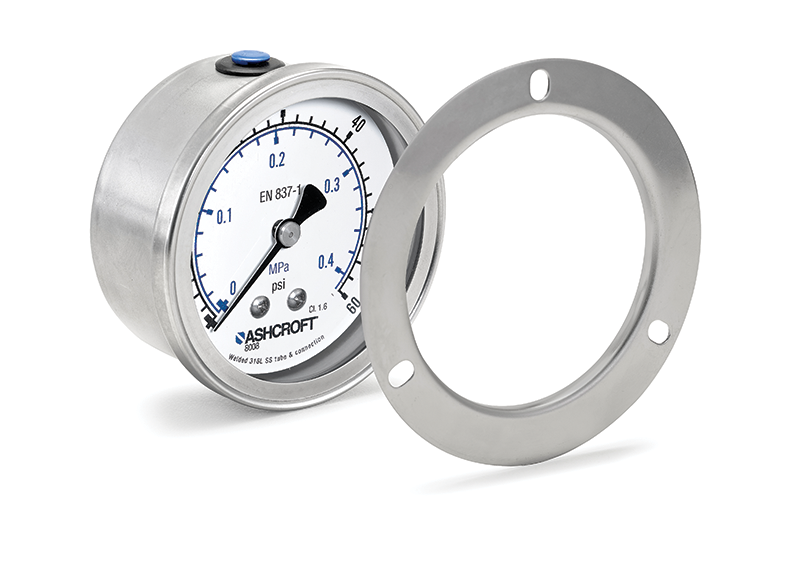 The Ashcroft 8008S offers a tamper-proof gauge with a crimped ring.
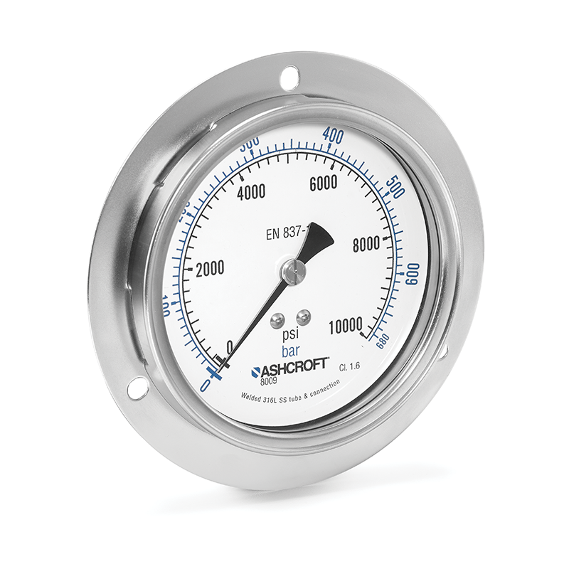 The Ashcroft 8009S features a removable bayonet ring that allows operator access to the unit to make calibration adjustments.
Both options offer a solid-front design if needed for additional safety. They are each UKCA, CE, and RoHS certified and meet testing requirements of EN837-1 and ASME B40.100 specifications for international use.
To learn more about consideration for selecting pressure gauges for your hydraulic application, free to contact an industry expert to get your questions answered.
Share this information.
Related Posts


Sponsor

Sponsors