Torque Division & Speed Synchronization Using 1:1 Counterbalances

By Tim Hodge, OEM Account Manager
and Steve Weber, PhD, CFPS, Regional Application Specialist, Sun Hydraulics, A Helios Technologies Company
In the unique world of mobile and industrial hydraulics we often find ourselves needing to synchronize torque and speed when using multiple motors. This sounds like a simple idea, and in a perfect world there would be a simple solution. However, we all know that very few things in hydraulics are as simple as they appear, fortunately, with the use of 1:1 ratio counterbalances, torque and speed synchronization can be easily accomplished.
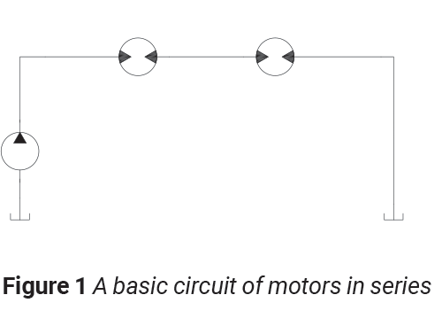
One of the earliest fundamentals we learn as we enter the world of hydraulics is the difference between parallel and series circuits. Once we have identified an application requiring speed synchronization of motors the first idea that pops in our minds is a series circuit. Simple right… Problem solved?
 Fortunately, around the same time we learned about series and parallel circuits, we also learned about efficiencies. Hydraulic motors are great at transmitting large amounts of power in a small package, but nothing is perfect in hydraulics and there are mechanical and volumetric inefficiencies to consider. As hydraulic designers, we must account for these inefficiencies. Electronic and proportional technologies are rapidly advancing, and we often use them for precise speed and/or force control. By using speed sensors, we could electronically close-the-loop and achieve precise control. This sounds great at first, but these solutions are typically expensive and require expertise to apply.
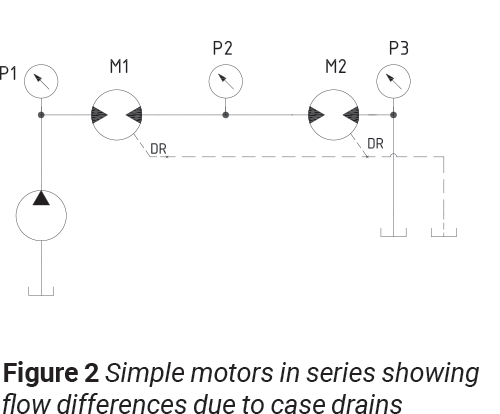 So how can we achieve speed synchronization in applications that are sensitive to price pressures? Let’s consider an example of a four-wheel machine that is propelled via two hydraulic motors. We would like both motors to turn at the same RPM with the same amount of torque. Once again, this sounds simply accomplished by using two motors in series with some means of controlling speed. The flow out of the first motor will be supplied to the second motor and they should have identical RPMs, correct? Unfortunately, due to ever present inefficiencies, this solution will have limited performance. The second motor will not be supplied the same amount of flow as the first due to volumetric losses internally through a case drain. Due to the flow loses, we would expect the second motor to turn slower than the first.
Now imagine we have 100% volumetrically efficient motors. If we have the same amount of flow entering motor number two as motor number one, should we not expect the same torque out of both motors? Unfortunately, motors are hydromechanical devices and even with advances in materials and machining technologies, having two motors with identical mechanical efficiencies is highly unlikely, if not impossible. Therefore, we must assume that the pressure drop required across each motor just to get it to turn without a load will be different. In a perfect world the pressure drop across each motor will be half of the pressure drop supplied to the first motor. In reality this is not the case.
TM1lbf-ft=p1-p2VD [psi∙cm3rev]1235
TM2lbf-ft=p2-p3VD[psi∙cm3rev]1235
The torque output form M1 and M2 are not equal since the flow into M2 is less than the flow into M1 because of losses like the case drain. Therefore, in order to have equal torque on both motors, some compensation for losses must be considered. Similar to hydraulic fan drives, another approach to motor speed control is to use pressure control instead of flow control. If we again imagine a 100% volumetric efficient motor and we were somehow able to get identical mechanical efficiencies, we should expect identical torque and speed if each motor is supplied the same flow. By using 1:1 pilot ratio counterbalance valves we can supply the same torque to each motor.

The circuit above shows two bi-directional motors in series with the addition of a 4-port vented 1:1 pilot ratio counterbalance valve with a mechanical setting of 400 psi. The counterbalance is used as a relief or compensator between P1 and P2. Port 4 is connected to port 2 which causes downstream pressure to be additive to the setting by a factor of two (1+Pilot Ratio) * Back Pressure. With a low setting of the counterbalance, the pressure at port 1 is 2 times greater than the pressure on port 2. The counterbalance will open when pressure between the two motors falls below the pressure upstream of the first motor, ensuring equal pressures and equal torques from each motor. The checks in the circuit prevent a short circuit back to tank and they also allow for a single counterbalance to be used for bi-directional motors in series.
 To further explain how this circuit performs, let’s assume both motors have a 1,000 psi induced load. When the directional control valve is shifted and flow is directed to port A and Motor 1, pressure will build to overcome the induced loads of both motors. If our motors were 100% efficient, we would expect to see 2,000 psi on G1 and 1,000 psi on G2, with 1,000 psi ∆P across each motor, creating identical torques and speeds. As reminded earlier, motors are not 100% efficient, therefore, we will closely examine the benefits of adding the 1:1 counterbalance valve. The scenarios below assume the system relief or pump compensators are set higher than the maximum achievable effective setting, and a return line pressure of 200 psi.
In Figure 4, as both motors begin to rotate, Motor 2’s 1,000 psi load and the 200 psi tank pressure will be present on port 2 of the counterbalance. Back pressure on standard non-vented counterbalance valves causes the effective setting to be increased as a function of:
Effective setting=Mechanical Setting+ 1+Pilot Ratio ∙ Back Pressure
However, in this case we have a vented counterbalance valve and pressure at port 4 has the same effect to the setting as backpressure on a non-vented counterbalance. We are using this to the modulate flow as the loads change by dynamically changing the effective setting of the counterbalance to maintain the p1 and p2 within a small difference in pressure. Starting with a 400 psi mechanical setting, we would expect the counterbalance to have an effective setting of 2,800 psi = (400 psi setting + ((1:1 +1)*1,200)). The counterbalance will remain closed as long as the pressure at G1 is below 2,800 psi. If both motors are rotating at the same rpm and torque with all forces in equilibrium, we would expect the counterbalance to remain closed with 2200 psi at the inlet of the first motor, 1200 psi at the inlet of the second motor and 1,000 psi pressure drop across each.
Considering volumetric losses due to motor leakage, the torque at motor B will be less than the torque of motor A because it has less flow available. Torque is a function of pressure, flow and RPM, and the counterbalance helps maintain torque and rpm by controlling pressure and flow through modulating makeup flow to the second motor in the series. This helps keep the torque nearly equal on both motors.
Tlb-ft=p[psi]∙5252N[rpm]
Php=p[psi]∙Q[gpm]1714
T[lb-ft]=p[psi]∙Q[gpm]1714N[rpm]∙5252
Since the torque available from motor 2 B is less, the torque requirement on Motor 1A and the pressure at G1 will increase. Simultaneously, the pressure at G2 will decrease due to less pressure drop at the lower flow, causing the effective setting of the counterbalance to lower. Once the effective setting is equal to G1, flow will be directed to Motor 2 through the counterbalance valve. The counterbalance will modulate as the effective setting varies due to changes in speed or loads, providing additional flow to Motor 2 while ensuring that G1 is two times greater than G2. By maintaining the same pressure drop across each motor, both motors achieve the same torque and RPM.
Application of hydraulic motors in series is useful when designing equipment but the hydraulic circuit must be carefully considered. Without some means of ensuring that torque is shared between motors, one motor could be overloaded and cause premature failure. The use of a vented counterbalance valve in a novel way provides a means of torque division to load the motors nearly equally in series.
Share this information.
Related Posts


Sponsor

Sponsors