Transforming Our Thinking About: Energy Units and the Cost of Control

By Dan Helgerson, CFPAI/AJPP, CFPS, CFPECS, CFPSD, CFPMT, CFPCC
I had a friend in college who lived in the city and was accustomed to driving aggressively in city traffic. He had been complaining about the fact that the brake pads on his car did not last very long and he thought the dealer might be selling him inferior products. One day, as I was driving behind him, I noticed that his brake light never went out. When I asked him about that, I found out that he drove with one foot on the accelerator and one foot on the brake. This provided great response time when doing the “bob and weave” in traffic, but did nothing to provide long life for the brake pads or improve his fuel mileage. There was a direct cost to his control system in the form of increased maintenance and fuel charges.
We are taught that there are three things that we control in our fluid power systems: flow, direction, and pressure. Of these three, directional control has the least impact on energy. It is usually understood that flow is required for velocity and pressure is required for force. We tend to separate flow and pressure in our thinking and design as though flow control is the only requirement for velocity. We need to understand that velocity control is power control. The velocity of a load, whether angular or linear, requires both pressure and flow, or in other words, power.
There is a certain quantity and flow rate of energy units that must be supplied to an actuator in order to make it move to do work at a specified rate. With pneumatics, these units are compressible while the hydraulic units are relatively incompressible. In both cases, a volume of pressurized units must be used to move an actuator. Once direction is determined, it is the flow rate and pressure that determine the amount of power directed to an actuator.
Hydraulically, with a fixed displacement pump that has been sized to control one actuator, the motor or cylinder velocity is fixed and only the pressure varies with the load. There is a higher pressure for acceleration, and then a lower pressure to maintain velocity. With both pneumatics and hydraulics, the available pressure must be set higher than the pressure for velocity in order to accelerate the load. Once the target velocity is reached, some type of power limiting must be employed to limit velocity. When there are multiple actuators under varying loads, or with a single actuator with varying loads and velocities, the energy source—be it an air compressor, an accumulator, or a pump— must provide the needs of the actuator with the greatest pressure requirement.
 Consequently, each actuator must have its own velocity control. The most common way to control the velocity is to use restrictive orifice type flow controls. The orifice is considered the means to limit the flow, which it does, but only because of the pressure loss. The power directed to the actuator is a combination of flow and pressure. We know we need the flow and so it is assumed that the only adjustment to the power is to reduce the pressure. The net result is that we design our fluid power systems to be controlled like my friend’s car. There is more power available than is required to do the work and so we “drive with the brakes on.”
A restrictive power control in a circuit could be a needle valve, a flow control, a pressure compensated flow control, or a pressure reducing valve. A proportional directional valve and a servo valve are also restrictive power controls as they are simply electrically controlled variable orifices, and are, by definition, energy consumers. With all of these, there is more energy upstream of the restriction than is required downstream and the excess energy is consumed by the frictional loss through the orifice. For many of us, this is understood to be simply the cost of control.
The Variable Displacement Transformer (VDT) replaces the restrictive power controls when there is a variable flow source. This could be a variable displacement pump, an accumulator, or an air receiver. The VDT provides the necessary resistance at the outlet of the actuator, not as a restriction, but as energy units that drive the transformer. One outlet of the VDT directs regenerated flow to the actuator inlet at source pressure, while the other outlet directs flow to low pressure, either atmosphere or the reservoir. The energy units drawn from the source are only those needed to power the load.
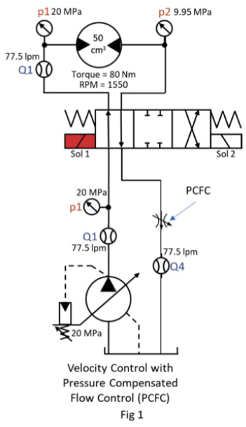
 For example, compare the velocity control by a pressure compensated flow control (PCFC) (Fig 1) with velocity control by a VDT (See Fig 2 on next page). The power source is a pressure compensated pump set at 20 MPa. The motor has a displacement of 50 cm3, torque load of 80 Nm, and an rpm of 1550. The motor requires 77.5 lpm to maintain the velocity. An effective pressure (p1-p2) of 10.05 MPa is needed to develop the torque.
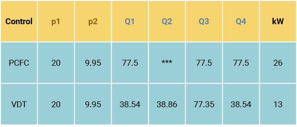
The common PCFC limits the power to the motor by adding a resistive load (putting the brakes on) of 9.95 MPa. The excess energy units are dissipated as heat. The pump supplies the full 77.5 lpm at 20 MPa, consuming about 26 kW.
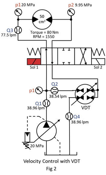
Using the VDT (Fig 2) the same effective pressure is needed but it is obtained differently. A resistive load of 9.95 MPa is applied as the 77.5 lpm exhausts from the motor. Instead of dissipating the resistive energy as heat, the flow and pressure are used to drive the transformer, directing 38.54 lpm to join the flow from the pump. The pump de-strokes, supplying only 38.96 lpm at 20 MPa, about 13 kW; precisely the flow of energy units needed by the motor. In this application, the VDT provided velocity control without wasting energy.
It is time to think differently and stop driving with our feet on the brakes.
If you have any questions, please contact Dan Helgerson at Dan@DanHelgerson.com.


