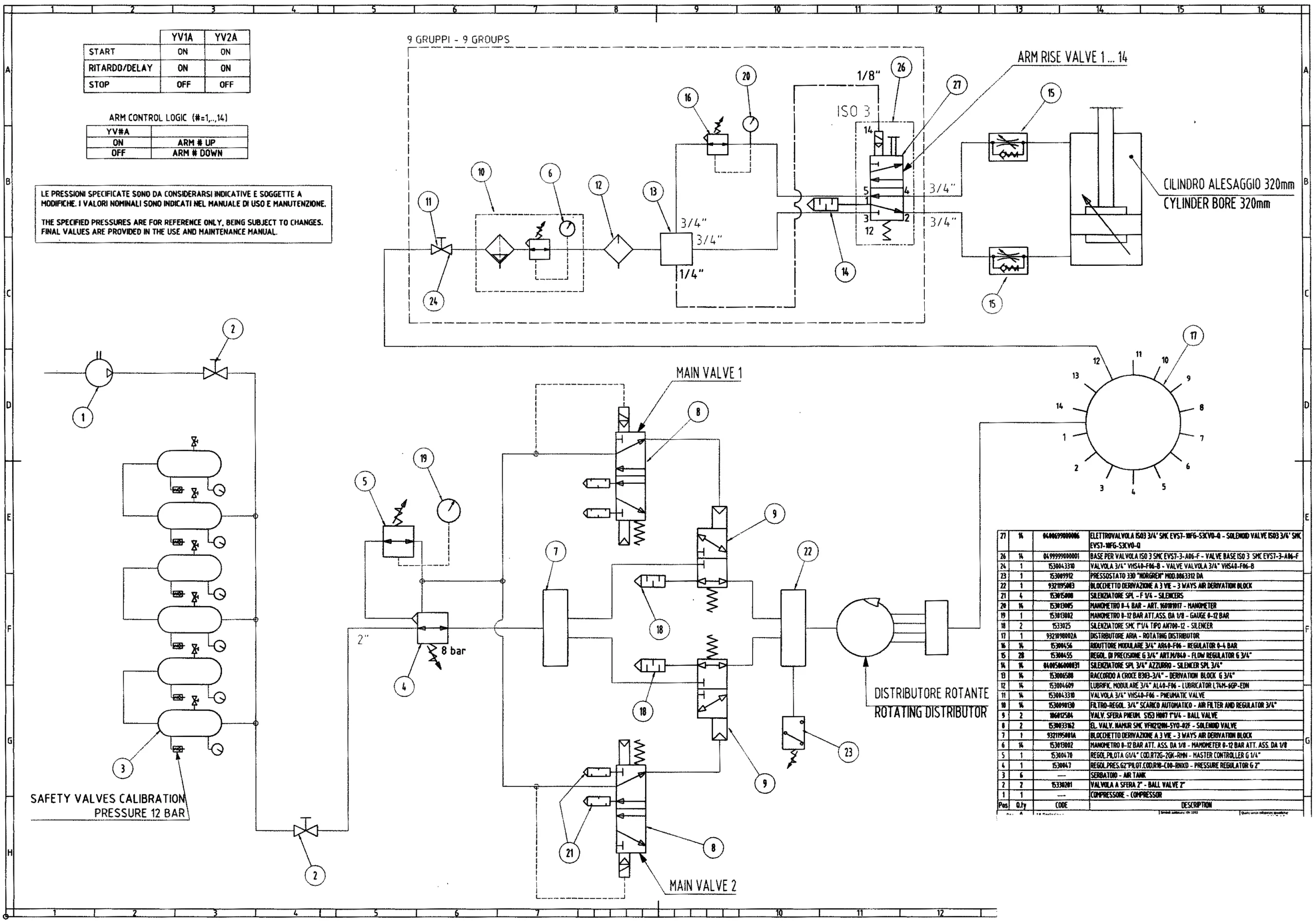
Recently a new ride was installed in an amusement park and it didn’t work on startup. The main cylinder would not extend. After the normal troubleshooting it was notice that valve #26 was a double solenoid controlled, pilot operated valve instead of what the schematic is showing without any change in the plumbing. I have two questions:

If you are a technician that troubleshoots systems, this would be a good one to show your boss why it can take so long to find the problem on a machine, especially when the schematics aren’t drawn correctly.
1. The pilot line was missing to the #26 valve.
2. I may not catch them all, but here are the ones that I caught.
a. Starting with the bottom schematic at the compressor – no relief valve or even a pressure switch at the tank to stop the compressor.
b. The pilot section of the first air regulator would not be using a normally open, air regulator (pressure reducing valve) to control the main air regulator. It would be a relief valve. I also question using the vent port for an air supply for the pilot of main valves #8.
c. Valve #7 is what? I believe that it is some kind of diverter valve, but it doesn’t have any way to shift it.
d. The two main valves #8 both have open ports so when the valves are shifted, air will exhaust. I’m assuming they should be drawn as a 3-way valve.
e. Box 22 evidently is another diverter valve, but why would you have a pressure switch on the pilot port of the valve. If #7 and #22 are only a connection, why would it be in a box?
f. It doesn’t make any sense to me to have two main valve circuits if you only use one at a time with no flow controls on either side. Could one be a backup circuit? If so, why doesn’t the rest of the circuit have backup capability? Another way to look at it is that they are using two 3-way valve to switch directions, but that doesn’t answer two lines going into #22 and only one out.
g. Next is the “Rotating Distributor” device. How can you change directions without two air lines feeding it, unless the controls are electric and they aren’t showing it.
h. Moving up to the top schematic and looking at regulator #16. I believe the sensing line should go back diagonally to outlet port of the valve to indicate that the sensing line is internal. Why would someone what to plumb the line externally in this application?
i. Valve 26 is the cause for the machine not to work. The valve is actually a double solenoid controlled, pilot operated valve and the second pilot line was missing going to the valve. A print like this is even harder when the print is so small and in a foreign language.