Two Walls Are Better than One: Multistage Telescopic Cylinders
By Tony Casassa, Application Engineer, Aggressive Hydraulics
Hydraulic cylinders are the workhorses of fluid power systems in a variety of industrial and mobile machinery. They have high power density, are durable, and can be leak-free even in challenging environments, providing many operating cycles before requiring service. Today’s hydraulic cylinders have features that make machines productive and easy to use. They operate smoothly over a wide input flow range, including very low flows and speeds. Cylinders are quite efficient, with both high mechanical and volumetric efficiencies. The high mechanical efficiency means the pressure required to overcome internal resistance is low. The high volumetric efficiency means the leakage flow rate across the piston is extremely low, which provides an additional benefit. When paired with a load-control valve such as a counterbalance valve, pilot-operated check valve, or low-leakage directional valve, a cylinder can hold a set position against an induced load for extended time periods. Consider, for example, an equipment rental yard with aerial work platforms in the air and booms held in place for days on end via load-holding valves locking fluid in a hydraulic cylinder.
One potential drawback to hydraulic cylinders is that the retracted length is always greater than the stroke. In most applications this length can be accommodated, but in some instances a shorter retracted length is a firm requirement or provides significant machine design advantages.
Types of telescopics
A potential solution for these applications is a multistage telescopic cylinder with two or more moving stages that can provide longer strokes relative to the retracted length. The most common type of telescopic cylinder is single acting, which extends with hydraulic power but requires gravity or some other external force to retract. If the cylinder must be hydraulically powered in both directions, the solution is a double-acting telescopic cylinder. However, a common mistake is expecting a double-acting telescopic cylinder to replicate the performance of a typical single-stage double-acting cylinder. If the different operating characteristics of a double-acting telescopic cylinder are not taken into consideration, the results can range from mild to serious machine malfunction.
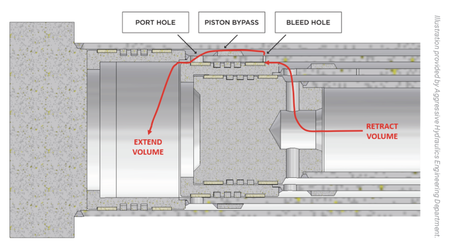
We will refer to the most common design of double-acting telescopic cylinders as “conventional.” This conventional design has a cross-drilled port hole in each moving stage to communicate flow and pressure in and out of the annular volume. Because crossing a hole while under pressure would cause failure to a typical elastomeric piston seal, split cast iron rings are typically used. Although these cast iron rings are robust and durable, they allow some bypass leakage, which allows the cylinder to drift under load. In our rental yard example, if a cylinder is replaced with a conventional double-acting telescopic cylinder, a boom left up in the air would slowly come down to rest on the ground. Likewise, an induced tensile load would cause the cylinder to drift out.
Potential issues caused by leakage
This leakage can cause other problems. The pressure required to move the cylinder against a load is dependent on the area and the load. The small gap between the cast iron piston rings and the bore is like an orifice of fixed size, in which the pressure drop across the orifice increases with flow. If the flow supplied to the cylinder is too low, the pressure drop across the “orifice” will be less than the pressure required to overcome the load. The machine operator may wonder why moving the control input is not causing motion. As the flow increases, the pressure drop also increases until there is enough pressure to move the load. Instead of a gradual increase, the initial cylinder movement may now be at a higher rate of speed. In addition to this instability or “jumpiness,” the operator or control system may be further confused as the relationship between control input and cylinder speed varies with load.
Another potential issue with leakage is more complicated, but understanding it could avoid a serious malfunction in which the cylinder stalls and will not retract. First, we will start with certain details of conventional double-acting telescopic cylinder design and operation. During normal operation, the largest stage fully extends first, then the next largest stage starts to move, and as it does the piston rings pass over a port hole. If the first stage is fully extended with the piston mechanically stopped at the head gland, this does not pose a problem. However, because all stages are pressurized simultaneously, it is possible for the cylinder to misstage and for a smaller stage to start to extend before a larger stage is completely extended. This is more common at higher flow rates and lower loads. It can be exacerbated by undersized port holes or variations in vee packing compression from one stage to another. If misstaging occurs, when a cast iron ring covers the port, fluid in the annular volume is trapped. The pressure applied to the blind end compresses the trapped fluid at an intensification factor equal to the area ratio. For a typical telescopic cylinder, this can range from 3:1 to 10:1. Even with a relatively low input pressure, the trapped pressure can easily exceed the burst strength of the cylinder. For example, an input pressure of 1,000 psi (69 bar) and an area ratio of 8:1 would result in 8,000 psi (552 bar) of trapped fluid in the annular volume. To prevent catastrophic failure, conventional telescopic cylinders often add a smaller port hole through each stage. If the cylinder misstages and the cast iron rings cover the main port, this smaller port allows the trapped fluid to escape. However, if the piston stops between the two ports and low flow is sent to retract the cylinder, the flow may bypass the piston by entering the smaller port and exiting the larger port to the extend side. The cylinder will stall and will not move the load until the flow increases and the pressure drop across the port holes exceeds the pressure required to retract the load and move past this point in the stroke. If the system does not have enough flow capacity, the load will remain stuck and require an external force to move.
One additional challenge with conventional double-acting telescopic cylinders is the location of the working ports. On a typical single-stage double-acting cylinder, both ports are located on the barrel, and it is simple to connect to the system. With the conventional double-acting telescopic cylinder, the retract port must always be in the end of the smallest moving stage, also known as the plunger. The extend port may be either in the main barrel or in the plunger end with the retract port. In many applications, it is preferred for the larger, heavier main barrel to be fixed to the machine and the smaller, lighter plunger to be attached to the moving machine member. However, to use the conventional design, a decision must be made between managing moving hoses or connecting the heavier main barrel to the moving member while consolidating hose connections on the plunger.
Solutions to design challenges
Fortunately, there is a solution to these design challenges that has many of the same benefits as a standard, single-stage double-acting cylinder. The key to this enhanced double-acting telescopic cylinder design, which we will refer to as a “double-wall” telescopic, is that the intermediary stage or stages are comprised of two concentric tubes with a flow path between them to communicate from the retract port located near the head end of the main barrel to all the annular areas. In this design, the pistons do not cross port holes, so low-leakage elastomeric seals can be used. This design addresses the challenges previously discussed.
- Hold a position against an induced load without drift when paired with a load-holding valve.
- Move smoothly across a wide flow range, even down to very low flows.
- Eliminate the potential for pressure intensification on the annular volume because the annular volume for all stages always has a free path to the retract port.
- Eliminate the potential for stalling due to bypass around the piston.
- Both ports can be located on the barrel to simplify hose connections. If desired, one or both ports can be in the plunger end.
- As an additional benefit for many applications, because of the positive piston seal and the location of the ports on the barrel, it is relatively simple to integrate a load-holding valve into the cylinder. This component integration can eliminate hoses, adapters, and brackets. More importantly, it greatly reduces the risk of unintended motion due to failure of a hose or threaded fluid connector, providing an increased level of machine safety.
It should be noted that there are some aspects of the conventional double-acting telescopic that this design does not address.
- Each stage has a different area. When supplied with a consistent flow, the cylinder speed will be different for each stage.
- To minimize the overall diameter of the cylinder, typically the clearance between the stages is minimized, leading to a higher area ratio than typical single-stage cylinders. This can lead to potential system design challenges:
- The return flow when retracting will be much higher than the input flow, requiring larger hoses, valves, and filters.
- If the extend side is pressurized and the exiting flow is restricted or blocked, there is a risk of pressure intensification.
Further, this design has two trade-offs that must also be evaluated to determine if it fits the application. Because each intermediary stage has two concentric tubes, the overall outside diameter is typically larger than with a conventional double-acting telescopic cylinder. Because of application space constraints and reasonable material availability, the double wall design is typically limited to two moving stages.
The second trade-off is the propensity to misstage during the retract phase. With a conventional telescopic cylinder, after the first stage fully extends, the piston of the subsequent stage extends, and the piston crosses the port hole. The annulus side of the first stage is now connected to the blind-end port instead of the retract port in the rod. As a result, when direction is reversed and the retract port is pressurized, the first stage cannot retract until the piston of the subsequent stage passes back over the port hole and pressurizes the annular volume of the first stage. The same is true for each stage, and this helps with consistent sequencing. On the other hand, with the double-wall design all annular volumes are always simultaneously pressurized. The retract sequence is primarily determined by the relative annular area of each stage. The stage with the largest annular area will retract first, then the next largest, and so forth. However, actual loading, backpressure, and pressure drop through the concentric tubes can alter the sequence. Before selecting a double-wall telescopic, the possibility of misstaging and related risks should be considered.
The value of double-wall telescopics
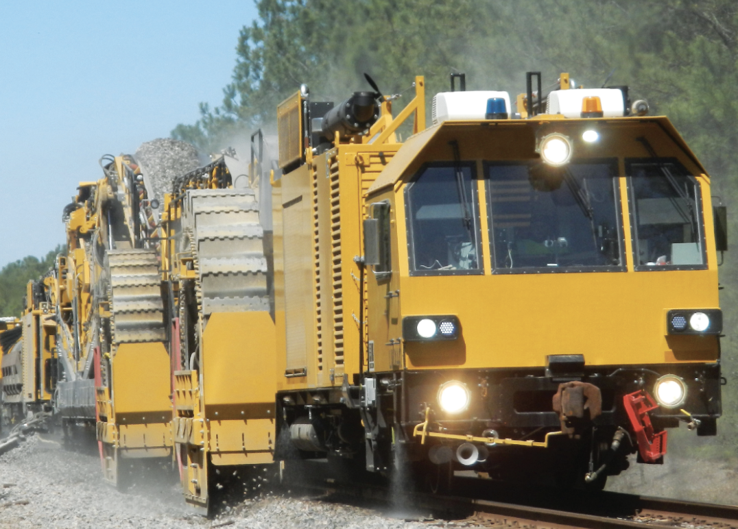
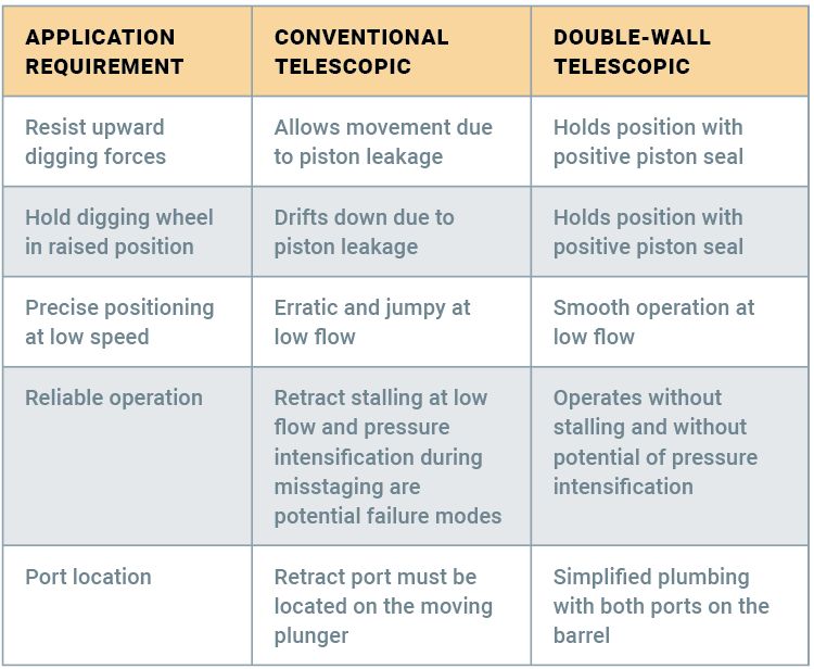
There are many applications in which the benefits of the double-wall telescopic provide real, tangible value to the OEM and end user. For example, consider a cylinder used to raise and lower a large digging wheel on a railway ballast maintenance machine. Due to space limitations, a two-stage double-acting telescopic cylinder is required to meet the retracted length and long stroke requirement. The cylinder lowers the wheel into a digging position and should resist digging forces trying to raise the wheel. Likewise, when the cylinder raises the digging wheel to pass a road crossing or for transit, it should not drift down due to gravity. The system uses a position sensor, PLC, and proportional valve to move the cylinder smoothly, often at low speed, to precisely hold or adjust wheel position. The railway must be closed to normal traffic during maintenance, so machine uptime is critical to complete the job in the set amount of time. Therefore, any potential risk of downtime-inducing stalls or pressure intensification is unacceptable. Because the main barrel is fixed to the machine and the plunger is fixed to the moving digging wheel, it is preferable for both ports to be located on the main barrel. As detailed in the table above, the double-wall telescopic outperforms the conventional telescopic in all aspects of this application.
When selecting or specifying double-acting telescopic cylinders, avoid accepting compromised performance to meet the retracted length and stroke requirements. Consider the option of a double-wall telescopic cylinder that provides the benefits of a telescopic cylinder with the performance of a single stage.
Share this information.
Related Posts

Law Firm: Manufacturers Must Consider Prescription Meds Case by Case
A Look at Uncommon Hydraulic Connectors
The Crucial Role of Cleaning & Sealing Hydraulic Hoses & Tubes
Electroless Nickel Plating on Hydraulic Fittings
Bluetooth Embedded Amplifier Enables Wireless Configuration of Proportional Cartridges

2015 Photo Contest
Sponsor

Sponsors