Basic Vacuum Cup Selection
By Daniel Pascoe
There are many types of vacuum cups available for use in vacuum pick-and-place systems. Some are designed with a particular application purpose while others are simply designed to offer a range of similar style models to the vacuum user: single bellows models from 5 mm through to 50 mm diameter, for example. This article is a basic explanation of fundamental cup choice to guide the user to a good starting point in a manufacturer’s catalogue index.
There are many shapes and sizes and also material choices, but fundamentally most vacuum cups offer the same end result: lifting of a load. The selection of a vacuum cup is often based on the weight of the part being handled. Although a sensible starting point, users often don’t realize the incredible amount a vacuum cup can lift until they work out the math. Even the smallest of vacuum cups offers a significant holding or lifting force.
Put simply, it’s rare that vacuum cups are not lifting because they are too small in size. It’s normally because of poor cup selection that is unable to seal against the load, or the vacuum generator is undersized, which in turn is unable to offer adequate vacuum flow in a circuit.
To calculate the holding or lifting force of a vacuum cup, two things are required: surface area of the cup plus the vacuum level being produced within it when it is sealed against the load.
The area of the vacuum cup is easy to calculate. If it is square, it is the length multiplied by the width. If it is round, use the equation πr² (pi x radius of the cup squared). [e.g. a 4-inch diameter cup has a surface area of 3.142 x(2×2) = 12.568in².]
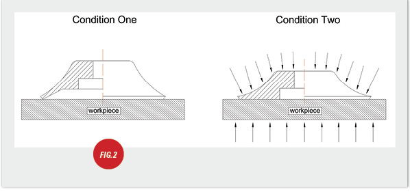
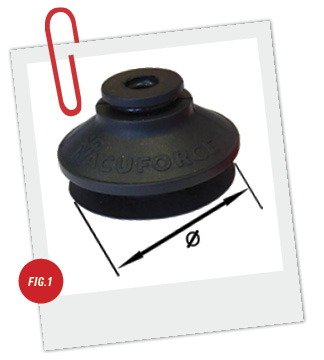 Fig. 1 demonstrates the only dimension this is applicable to: the sealing lip. What is important to understand is that the shape or height of the vacuum cup does not influence the lifting force. It is the amount of higher atmospheric pressure pushing down on the cup illustrated in Fig. 2.
Condition One is the vacuum cup at rest without the vacuum-generating device connected. When the vacuum generator is turned ON (Condition Two), the cup is “pushed” down onto the work piece and the corresponding atmospheric pressure underneath the work piece pushes up. The work piece is now “clamped” by the two higher atmospheric pressures.
If the atmospheric pressure is 14.7 psi (pounds per square inch) and the atmospheric pressure has been reduced by 10 psi (a vacuum is the difference between two atmospheric pressure levels), the differential pressure offers a holding force of 125 lbs when using a Ø4″ vacuum cup (12.568 x 10). If the differential is higher (more vacuum), then the holding force is increased and consequently lower if the differential is less.
It does NOT matter what shape the vacuum cup is. It is the surface area of the sealing lip that determines the holding force.
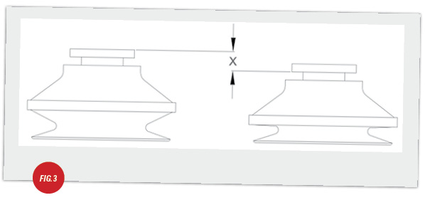
Figs. 1 and 2 show a “flat” cup. One of the most popular cups, particularly in models less than Ø2″, is a bellows cup. The single biggest advantage of a bellows cup over a flat cup is the compliance it offers in height adjustment. A flat vacuum cup has to be positioned accurately in a pick-up and put-down application, whereas a bellows cup offers its own level compensation in its design. In destacking or stacking applications where the datum point is continuously changing, the bellows cup is particularly beneficial. Fig. 3 demonstrates this height difference indicated by “X”. Depending on the design of bellows cup and of course the amount of bellows, these cups can offer considerable compensation for height variance of the load being handled.
The disadvantage of a bellows cup compared to a flat cup is the stability of the workpiece during transfer. The flat cup offers a datum face to locate the workpiece securely, which is particularly important during lateral movements such as in steel plate transfer on a stamping line, for example. Furthermore, a bellows cup should not be used in vertical lift application as shown in Fig. 4.
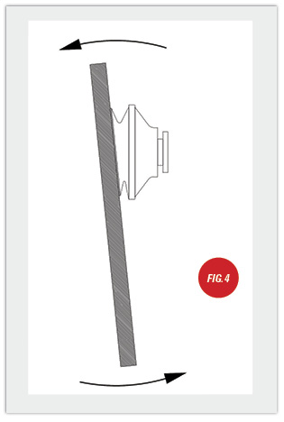 Even though the workpiece is clamped against the cup, the possibility of the part wanting to swing or “peel” away from the cup during the lift cycle is greatly increased as the cup does not locate the workpiece securely against a datum face, unlike a flat cup.
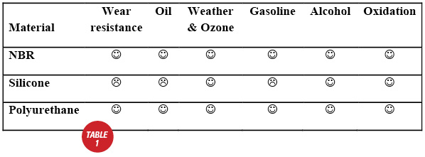
Material choice is relevant for a number of reasons. The most common reason for material choice is based on the need for flexibility to deform against contoured or rough surfaces where a softer compound is required or where the material needs to resist chemicals on the surface of the workpiece such as oil in steel stamping. Table 1 offers a basic compliance comparison of the two most common vacuum cup materials: NBR and silicone.
Certain materials should never be used on certain applications. Silicone compounds should never be used to handle products that are to be painted, such as automotive body panels, as it will leave a residue of the compound on the workpiece, and paint will not adhere to the metal surface correctly. In fact, in most stamping plants, silicone is prohibited in case of cross contamination during maintenance procedures involving cup replacement. This is the same for decorative stone handling such as granite or glass transfer, which will both be permanently marked by silicone.
The most common material is NBR, or Nitrile rubber. This material offers a very good starting point in respect to Durometer, which is normally about 50-60 from most manufacturers. Silicone and natural rubber tend to be softer, but do not offer the wear resistance of Nitrile rubber.
Most vacuum cups will work, and most materials will offer basic performance. However, the correct selection of style and compound will offer considerable savings in production, life, and reliability. There is lots of choices, but as in most component choice, basic criteria such as the aforementioned gets the user very close to final selection very quickly.
This article is intended as a general guide and as with any industrial application involving machinery choice, independent professional advice should be sought to ensure correct selection and installation.
Daniel Pascoe is President of Davasol Inc, an independent industrial consultant specializing in online brand presence and industrial e-commerce stores, with clients across North America and Europe, one of which is Vacuforce LLC (www.vacuforce.com) a manufacturer and distributor of vacuum components for whom this article was co-written with.
Daniel can be reached via www.davasol.com or directly at dpascoe@davasol.com. Find Vacuforce on twitter.com/vacuforce

